02/28/2017
moog music hackathon 2017
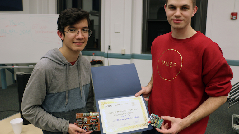
I recently participated in 2017 Moog Hackathon with my great friend and synth/electronics genius Victor. Before I write anything here I'd like to make it clear that Victor really carried most of the weight for the team, and while I built some circuitry of my own that I was pretty proud of, Victor's ideas and performance chops are probably what won us the second place prize. He's been building synths and making crazy noises since high school, some of which are documented on his YouTube channel. He's also recently been doing some shows under his Root Locust moniker, there's a track you can listen to on Bandcamp.
hackathon objectives
Moog distributed to every team their semi-modular Werkstatt-01 synth to hack around. The semi-modular nature of the synth allowed for teams to interface with the synth using control voltages (CV) to control certain synthesis parameters. The judging was based on three criteria: conduciveness to musical expression, technical complexity, and artistic presentation. A lot of hacks focused on creating a completely new instrument in the classical sense, creating a new interface to "play" the Werkstatt. Victor and I were interested instead in enabling the Werkstatt to make completely new sounds through the use of analog circuits. So that's what we did.
what we built
The first two circuits I built were a peak and trough circuit, using Ken Stone's design. These were the first circuits I've ever built that were meant to modify audio, which made me regret not doing so earlier. I got pretty distracted making new sounds for about an hour or so after constructing them on my breadboard. After making sure they were in working order, I translated them onto a piece of perfboard that we were going to build all of our circuits on. I was pretty rusty at perfboarding, but I got better as the weekend went on.
These circuits are relatively simple but are really interesting to see work. Of N-inputs, the peak outputs the highest input voltage and the trough outputs the lowest input voltage. The circuits begin with either a diode-or or diode-and, and then are followed by a PNP or NPN emitter follower to reverse the diode drop or rise from the input. To reduce the emitter follower's beta-dependence a simple single-transistor current source is used to bias the emitter followers.
Victor built two designs based around Ken Stone's smooth and stepped generator and Grant Richter's analog tracking generator. What was most impressive is that while I was still trying to wrap my head around what each circuit did (let alone how they worked), Victor was busy modifying them to make them work with the components he had on hand. The sounds that Victor made blew mine completely out of the water, even when they weren't fully finished yet. Here's a video of one of the first things Victor got working, a random melody generator.
The last thing I built was a basic arpeggiator. I originally wanted to use a single 8-bit shift register, but I had none. I did however have four dual d-flip-flops. I wired up a classic 555 timer in an astable configuration to act as a clock source, along with a potentiometer to adjust the clock frequency. Each flip-flop output was wired to the input of the next, forming a chain of flip-flops. The input to the first flip flop was exposed on a female header socket. I mounted a pushbutton to the board to act as a gate output, which was also exposed on a header socket. The button could be connected via the headers, or the input to the first flip flop could come from another source (such as the Werkstatt).
The outputs of all of the flip flops were connected in a passive voltage summing configuration (eg. all connected to one another through a large series resistor). I could have buffered the output, but as most synth inputs are designed to be high impedance inputs, buffering is less important than it seems. Each flip flop output also lit up an LED. This let you see the bits "flow."
Here's a demo of the circuit when it was working on a breadboard. The oscilloscope shows the summed voltage output, which you can see "stepping" up and down. The input to the first flip flop is a gate output from the Werkstatt. When a key is pressed "ones" are shifted in. The output of the circuit is input back to the Werkstatt where it is used to modify the oscillator frequency.
Here's a video I took after the hackathon of the board I assembled. It's quite dark, and there's no sound. I might upload some more photos of the board later. The LED in the top left is the oscillator output and the LEDs on the right show the state of each flip flop output.
other performances + recap
Overall, I really enjoyed participating, even just getting to spend the weekend hacking away with a soldering iron was an enjoyable experience. It also gave me an appreciation for analog synthesis and some of the really interesting/elegant circuitry that is used to achieve strange effects. I'm really excited to start to play around a bit more with the Werkstatt I got to take home from the event.
I was also just blown away by the other hacks that were put together within the weekend and the other performances. There was everything from spinning platters to accelerometer-driven microphones and electronic bagpipes. I strongly suggest checking out some of the other groups in this recap of the event.