02/9/2026
overdue update
The last time I uploaded anything here was over 9 years ago, which is crazy. If you just want the career updates:
- After college, I did three months at VRGluv before getting let go - I got scammed almost as bad as the 440 backers!
- It took a good few months of job search, but I landed a gig on Google's wearbles team, and moved from Atlanta to San Francisco in 2018
- In the summer of 2021 I joined Humane, signing my offer before being shown the product concept (never doing that again)
- After just over two years, I left Humane to travel and focus on my own projects
- I've been consulting since 2024!
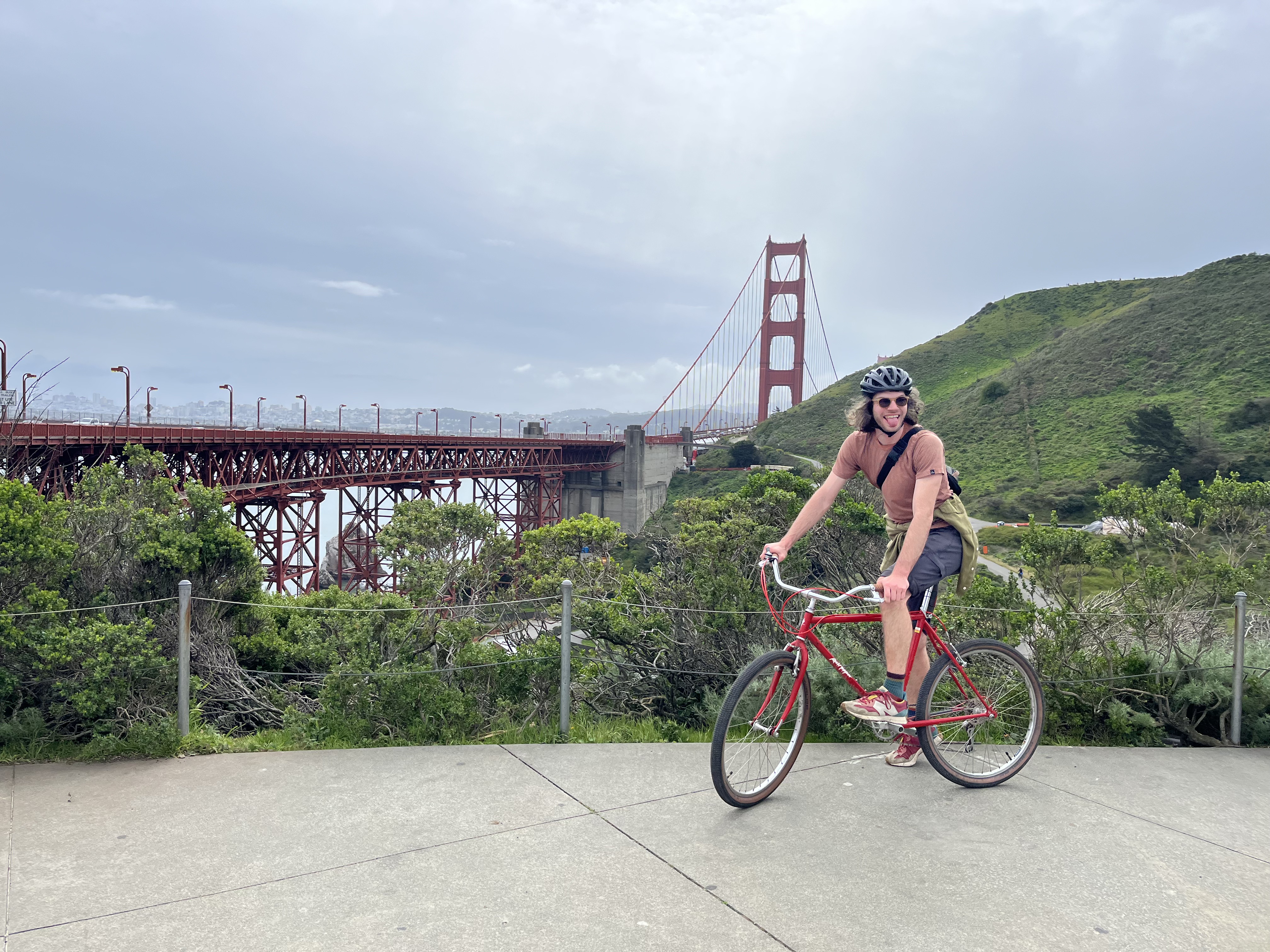
With that out of the way - living in the bay has been a blast. I've ridden into sunsets on bike trails in the Marin headlands, skinny dipped at Baker Beach in the freezing Pacific, and boarded through knee-deep powder in Lake Tahoe. I've toured hidden tunnels beneath the city, played drums in garage shows with my band, danced away nights at incredible venues, and caught sunrise sets at Burning Man.
I am a drastically different person than who I was when I arrived here, and for that, I am eternally thankful. Thankful to all the incredible people I've met from all walks of life that have taught me so much. Thankful for the environments and experiences that have challenged my ways of thinking. Thankful for the love I've found and the love I've lost. I wouldn't trade these years here for anything.
With that out of the way.. I'm still doing projects! It's kind of my thing. I'll try and post some soon!
06/4/2017
vw brake and suspension overhaul
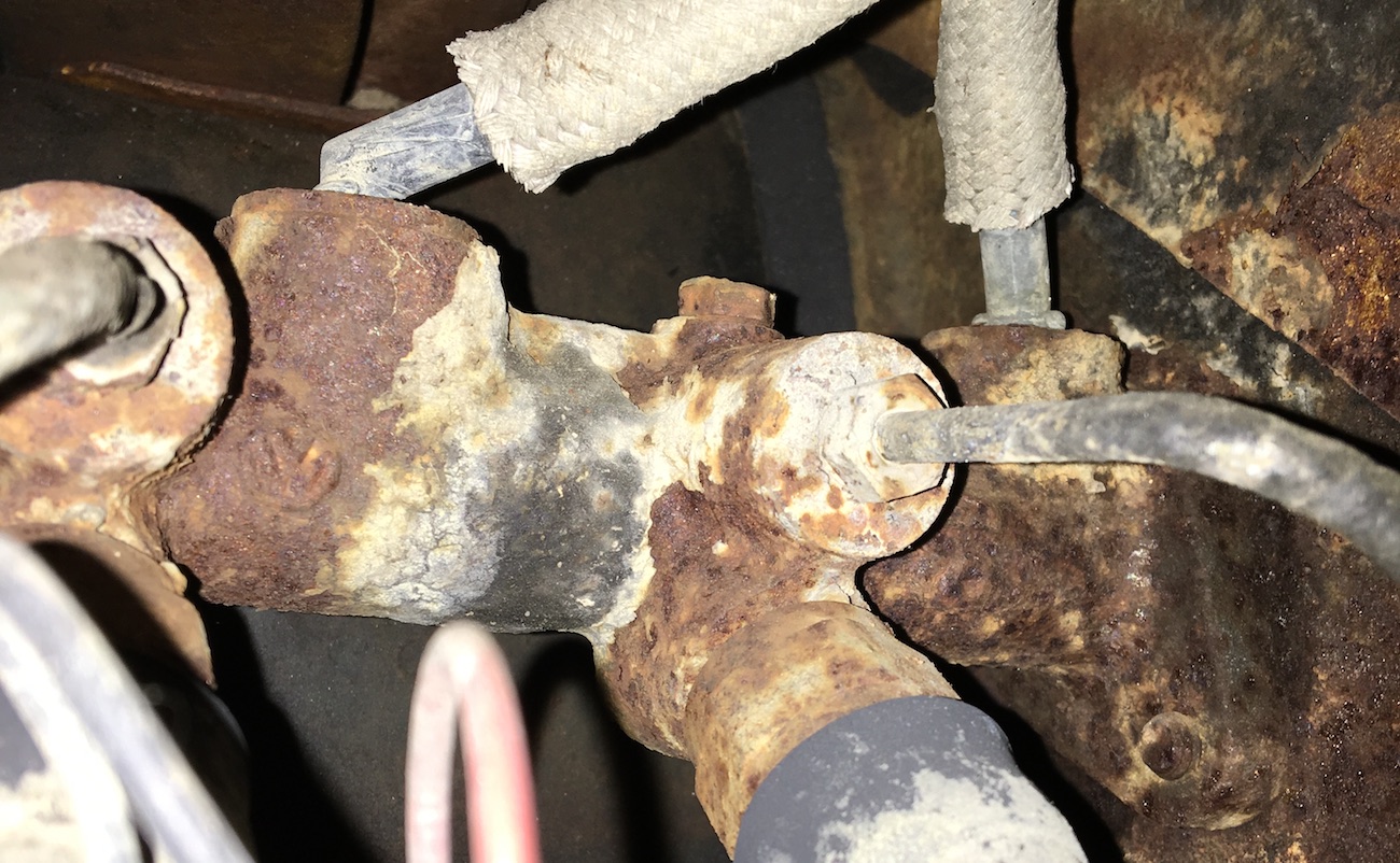
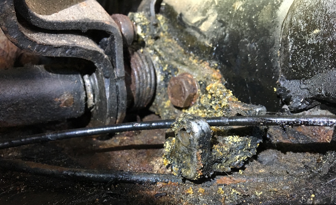
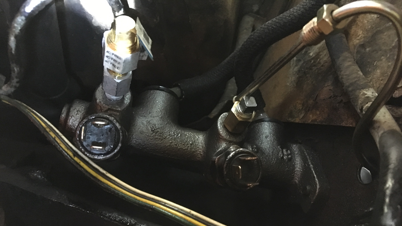
A few weeks ago (at the end of May) I started to feel my brake pedal sinking towards the floor, which obviously was a bad sign. It took a while to notice a loss of braking authority and I stopped driving. What I noticed was the front brakes not functioning as strongly as the rear brakes, so I started looking for a leak. While I've been told it's not common for the master cylinder to be the culprit, that's where I started. I found the issue almost immediately. There was a strange goop directly under the master cylinder pin, which smelled distinctly of brake fluid.
I got a AAA tow from my apartment back to my parents house, and the work began, which quickly devolved into a lot more than a master cylinder replacement over a single weekend.
cleaning up the pedal cluster and floorpan
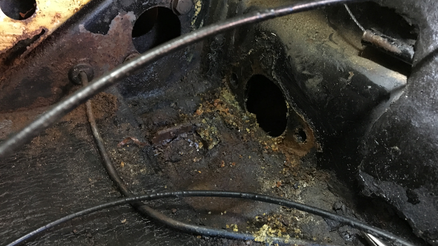
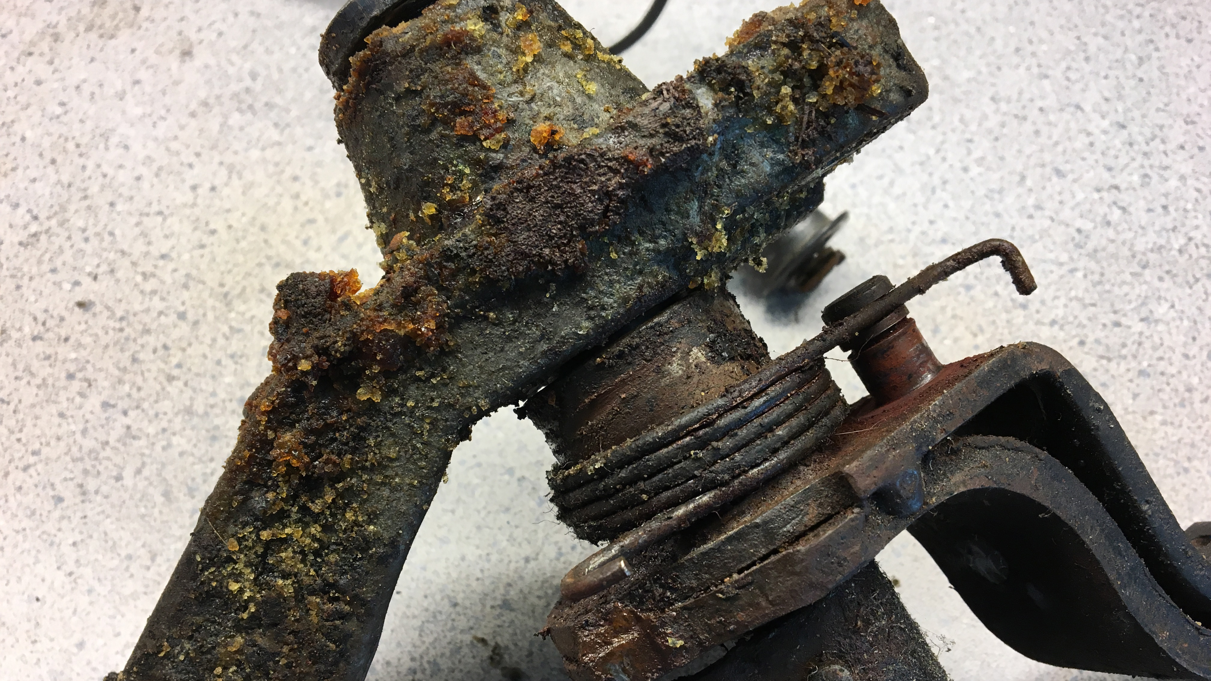
I started by removing the pedal cluster and the old master cylinder, which was very crusty. It looks like it's been there a while. Not sure if it's original (I think that would be quite a miracle), but seeing the VW logo on the cylinder was a nice little surprise.
These strange crystals had formed on the pedal cluster, alongside a good amount of rust and dirt. I might be wrong, but I think the crystals might be crystalized brake fluid.
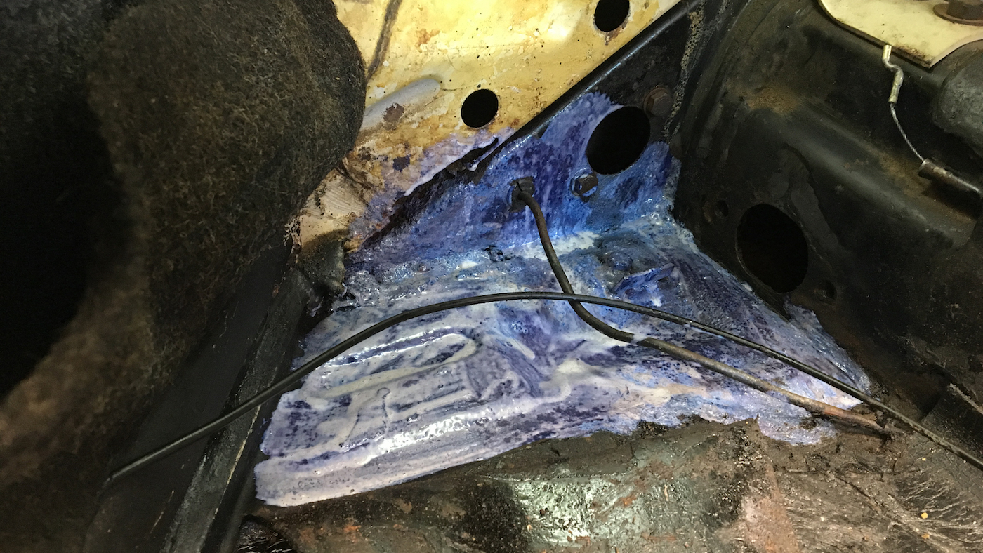
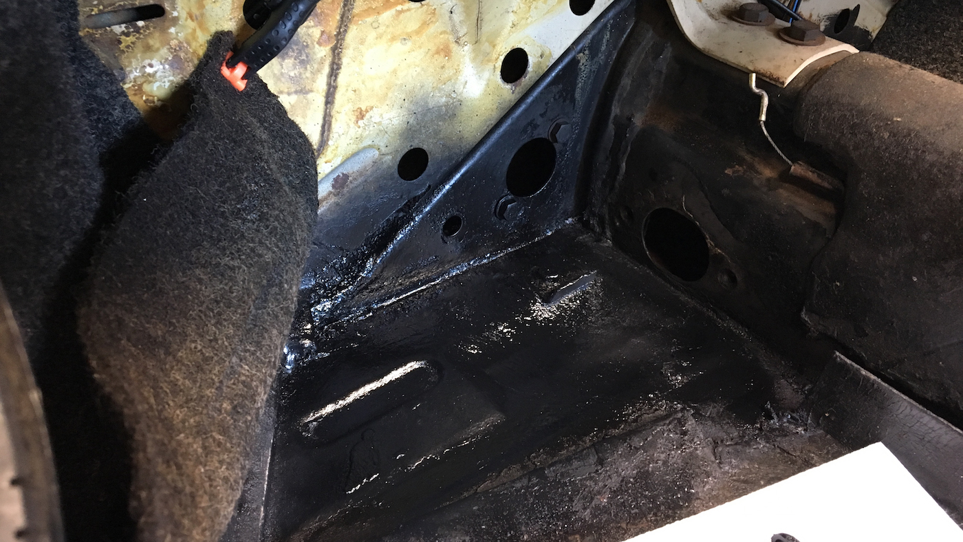
I cleaned out all of the grime that was on the floor pan underneath the pedal cluster with a vacuum and a wire brush. There was some rust forming on the floor pan and inside of the front frame cross brace, so I painted it with some rust converter, which turns the rust into an black coating that inhibits rust and can be painted. It paints on white, then turns into a black surface. After the rust converter had done its magic I gave the area a coat of black Rust-Oleum spray paint.
I completely dissassembled the pedal cluster and cleaned all of the parts with some degreaser and a wire brush. During reassembly I applied new grease to the shaft of the clutch pedal hook.
installing the new master cylinder
I don't have many photos of the process, but at this point I ran a new hard brake down the outside of the body tunnel (inside the car). It took quite a bit of effort to get all of the bends in the right place. There's a tee in the rear which splits the brake line off to the left and right brakes in the rear. It's in the worst place, sitting on a flimsy l-bracket pushed up against the bottom side of the luggage tray (part of the body of the car). It took a lot of attempts to get the new brake line bent in such a way that it would thread into the connector.
I tried one or two different bench bleeding methods but wasn't having much success. I don't have any photos of the process because I was too busy trying to keep brake fluid from spilling everywhere. What I ended up doing (at the suggestion of my dad) was installing the cylinder in the car, installing the pressure switches, plugging off the two outlet ports, and connecting the cylinder to the reservoir. I used a vacuum tool to pull a slight vacuum on the fluid reservoir while I pushed in the piston in the master cylinder. This pulls all of the air (or most of it) out of the cylinder.
The main brake line I got in the brake line replacement kit was a bit too long, which made the bend near the master cylinder a little more extreme than I would have liked. But it'll be fine.
I installed the pedal cluster back and bled the brakes, and there still wasn't a great amount of braking power. I think in the end I didn't bleed nearly as much air out of the system as I should (I also didn't set the star adjusters to get the shoes as close to the drums as they should be), but at the time I figured that the lack of "hardness" in the pedal was a sign that the brake shoes needed to be replaced. I hadn't replaced them since purchasing the car four years ago, and I had no idea how old they were, so I figured now would be the time to do a brake overhaul. Maybe a premature conclusion on my part which made more work than necessary, and I probably should have stopped to assess the situation a bit more, but what's done is done.
strut and shock removal
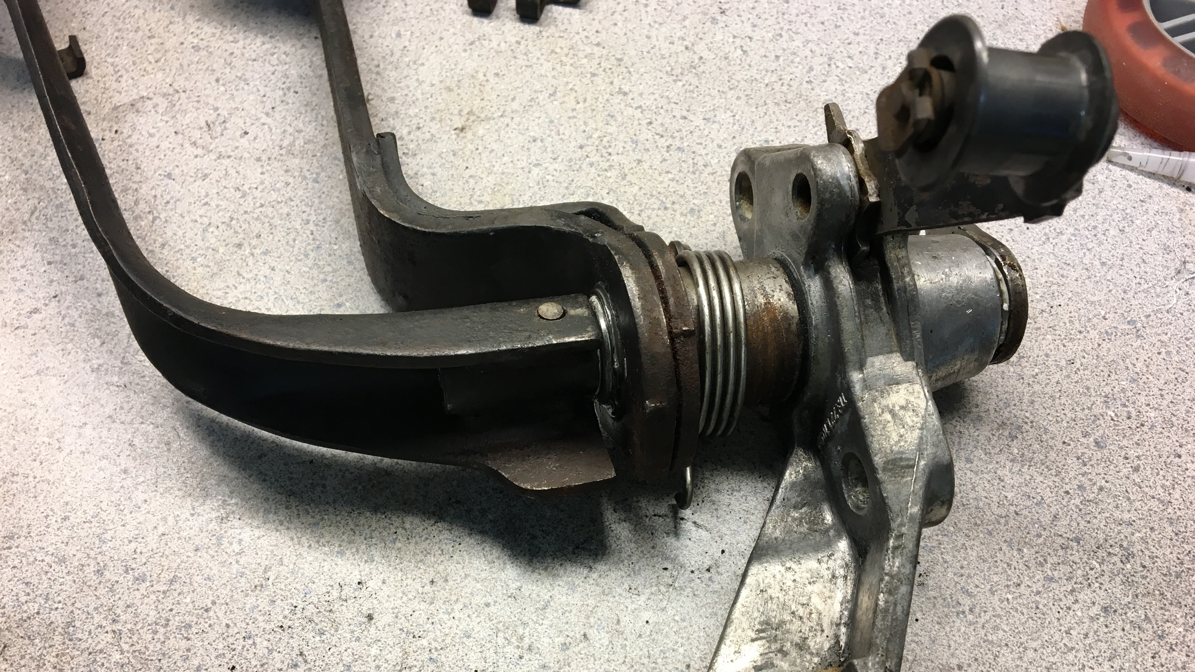
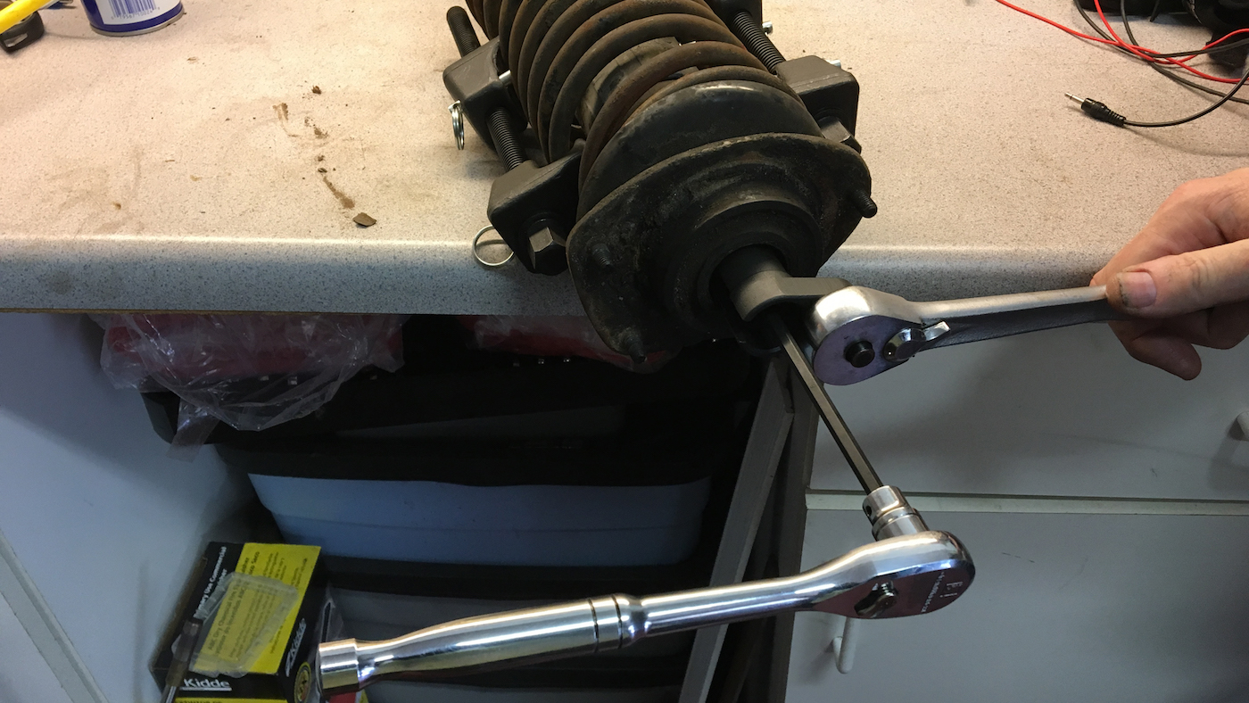
I removed all four brake drums, shoes, springs, slave cylinders, and backing plates. At which point, I thought it would be a good time to replace my struts and shocks, since I had such easy access to them. In the front, this involved unbolting the steering kuckle from the ball joint and unbolting the strut tower bearing from inside of the trunk. My dad was a huge help with this. We used a spring compressor to loosen the tension on the spring to remove the entire strut tower assembly as one unit.
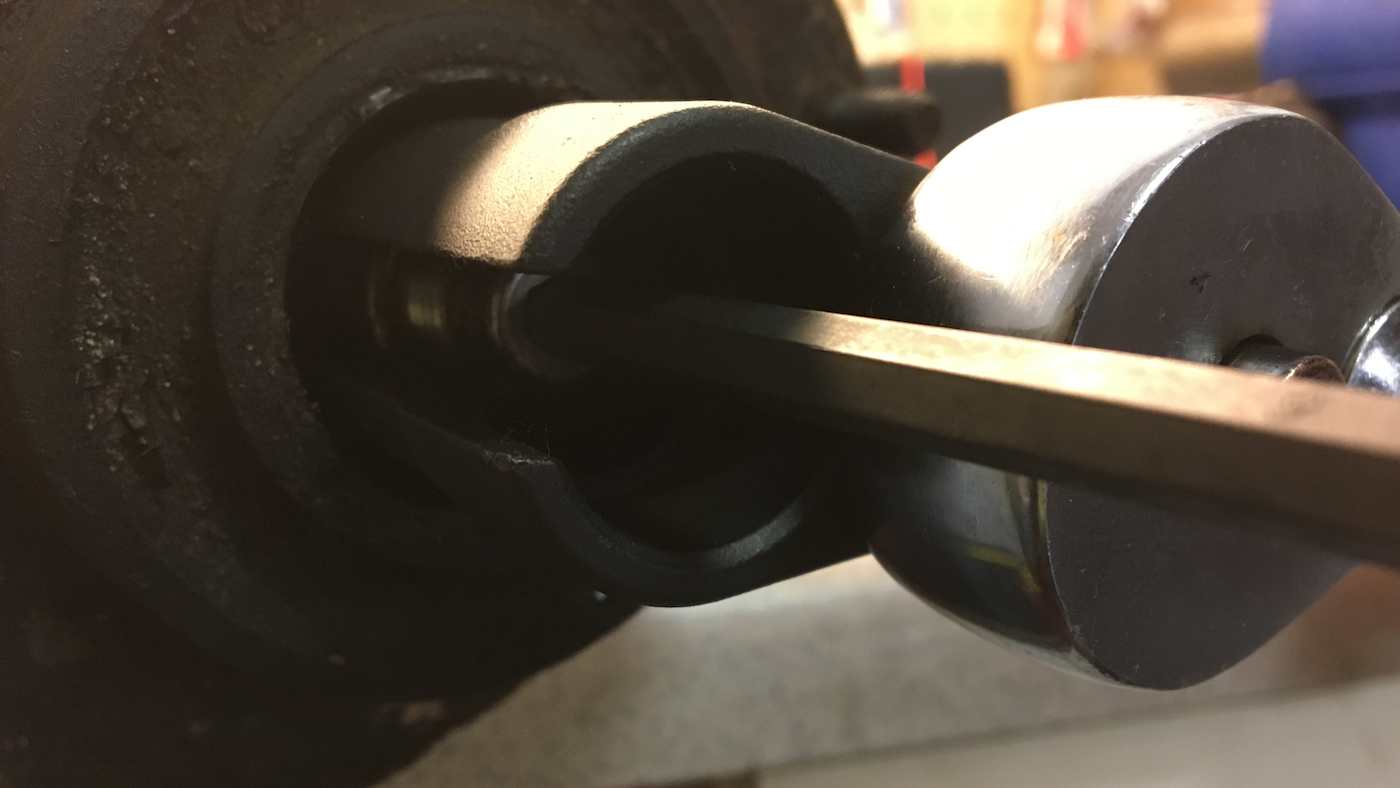
To remove the nut that holds the strut piston inside the strut tower bearing (which allows the strut to rotate while still being connected to the frame of the car) an offset wrench is typically used. We didn't have one large enough, but my dad did have this kit of offset sockets that are intended for removing O2 sensors, which worked great.
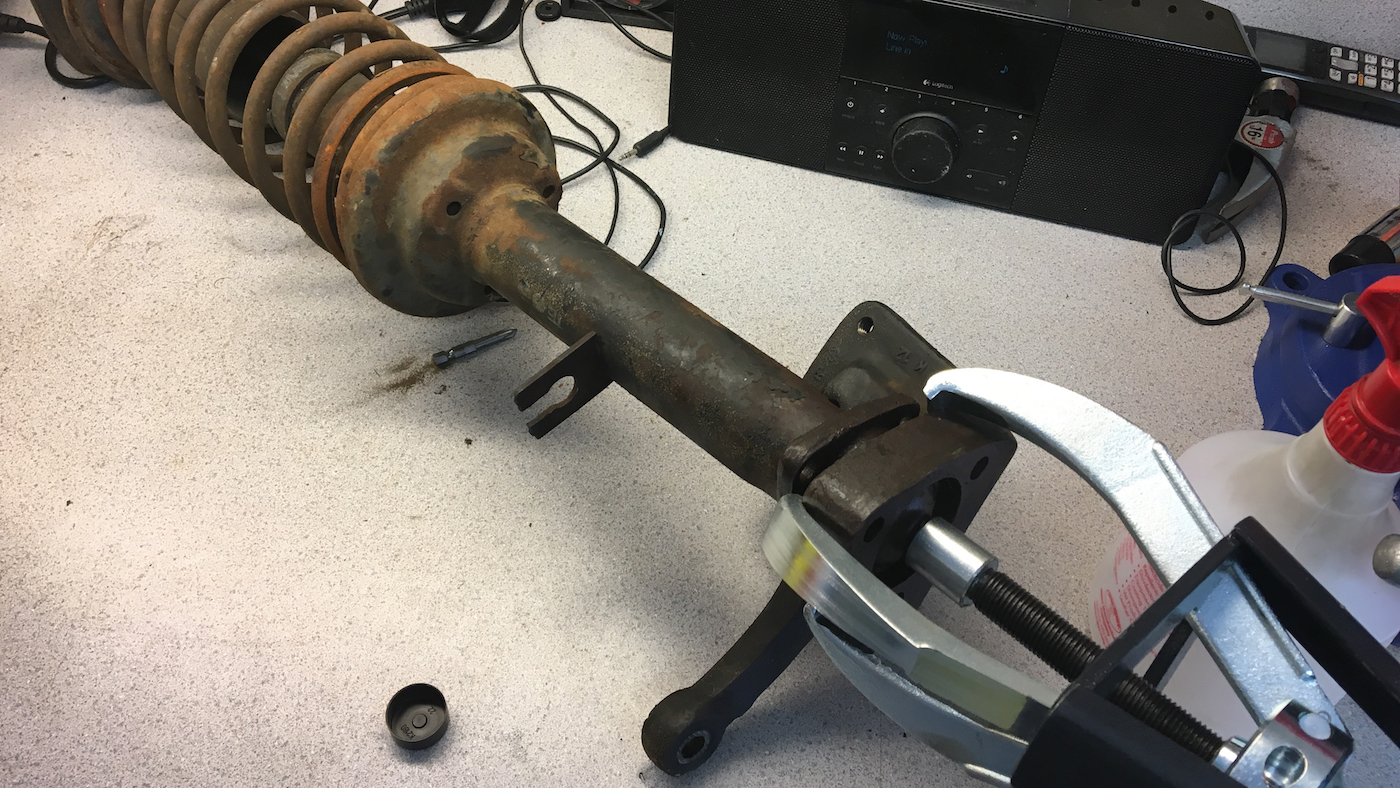
The bottom of the strut tower was stuck inside the steering knuckle and didn't want to budge. My dad and I tried lots of prying and PB Blaster before getting out the torch and a the big puller to get it un-stuck.
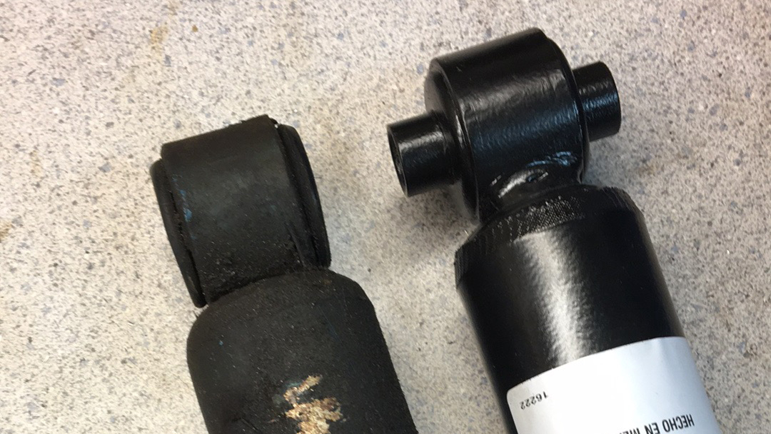
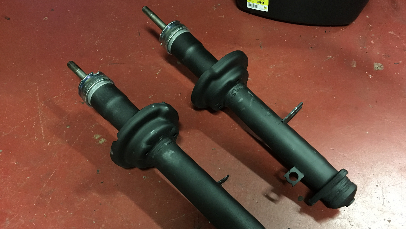
Removing the rear shocks was a much easier process. Two bolts and they were out. When removing the rear shocks, I noticed a different between the existing ones and the replacements I purchased. The replacements had a longer "tube" in the bottom mount, which would not fit into the existing mount for the shock, or so I thought. Here's what the new shock looks like compared to the old shock, and here's how the old shock was mounted into the car.
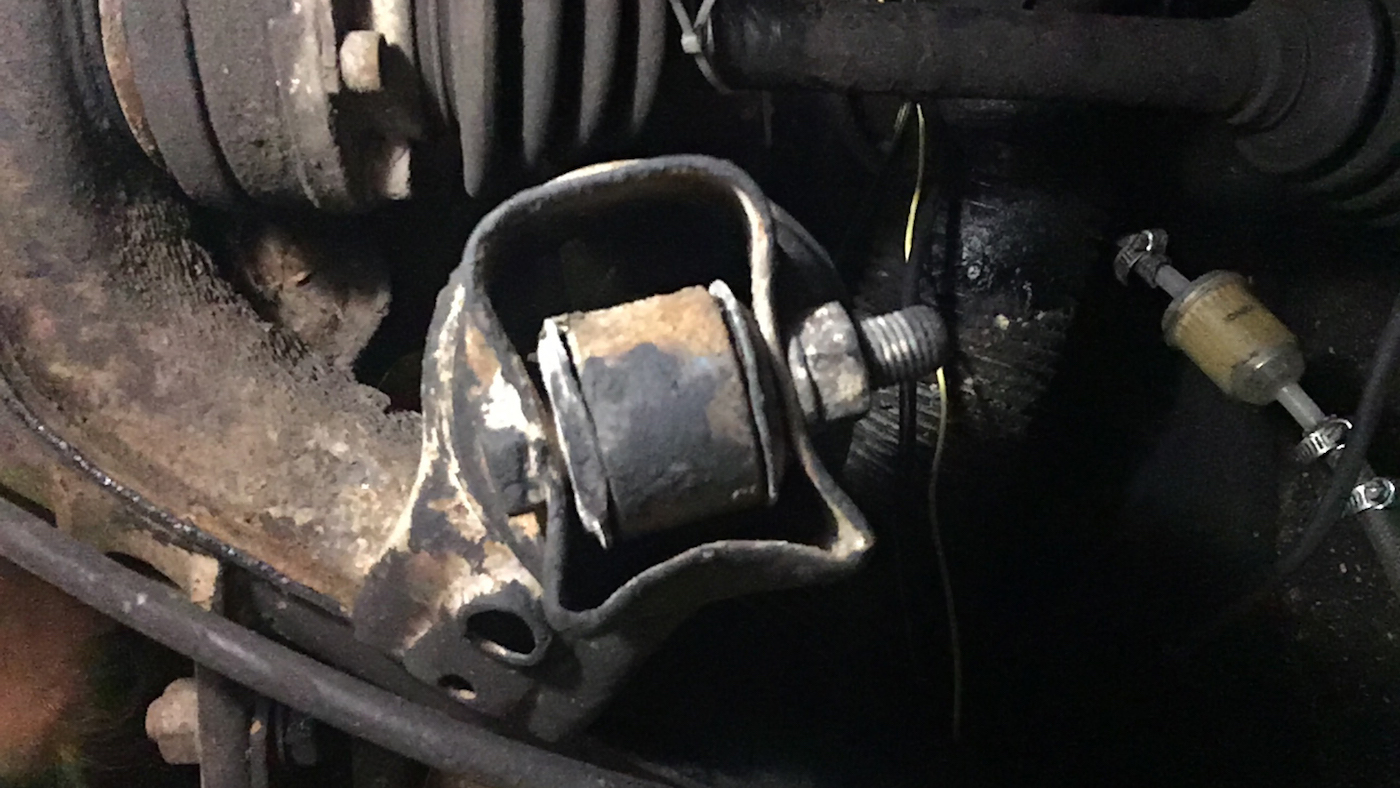
This didn't seem right, and I was pretty certain I had purchased the right shock. I messaged a member of my local VW group and asked him what his rear shock mount looked like, sending along the photos above. He affirmed my fears. A previous owner or shop had purchased the wrong shock, and instead of finding the correct part, dropped it in and tightened down on the bolts bending the mount out of its square shape. I ended up fixing this, which I'll show in a bit.
After removing both struts and both shocks, it was easy to tell they needed to replaced. All of the oil had leaked into the strut towers from the two struts and they were very easy to move compared to the new struts. The old shocks were potentially in better shape but they were still in very poor condition.
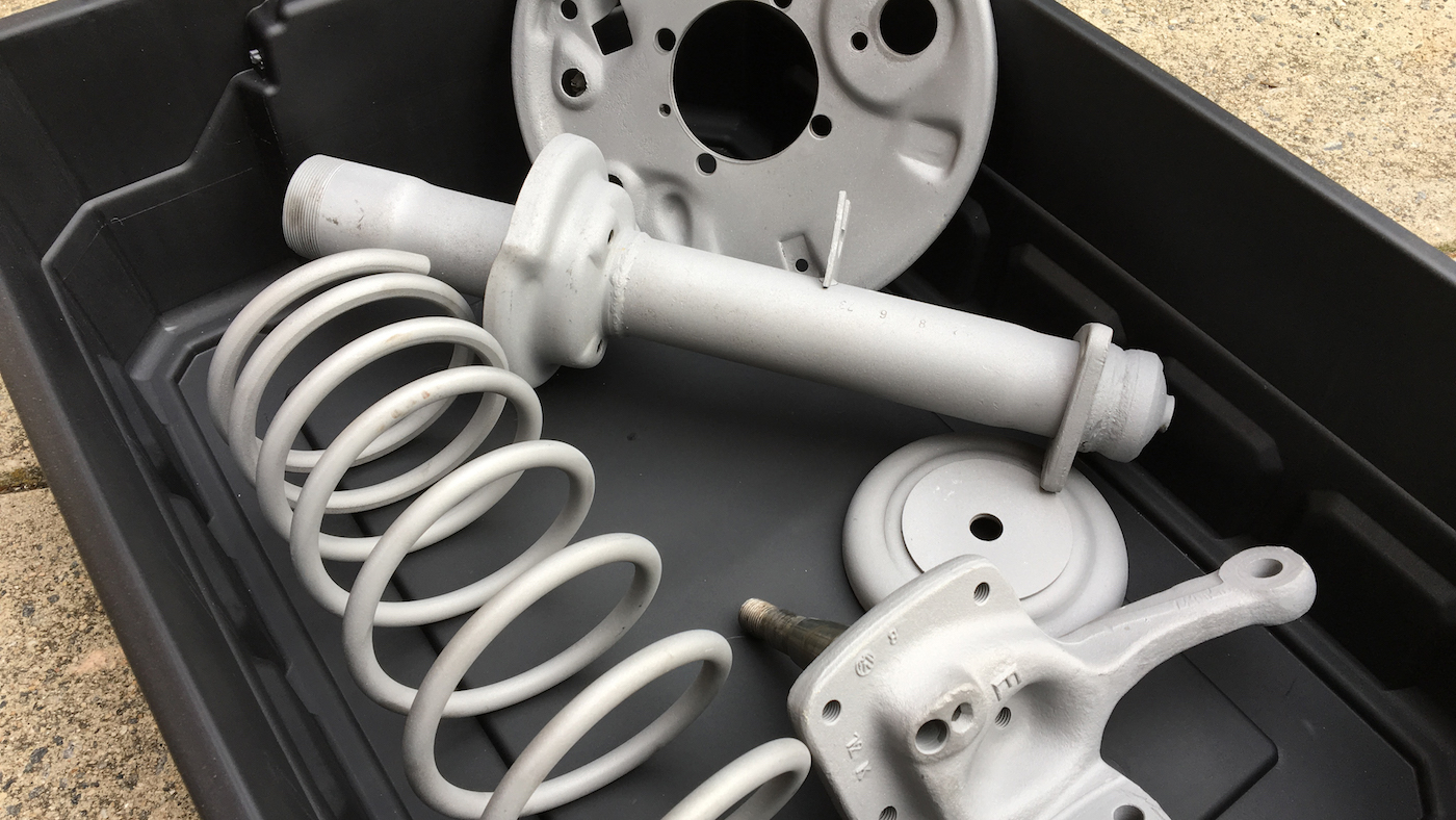
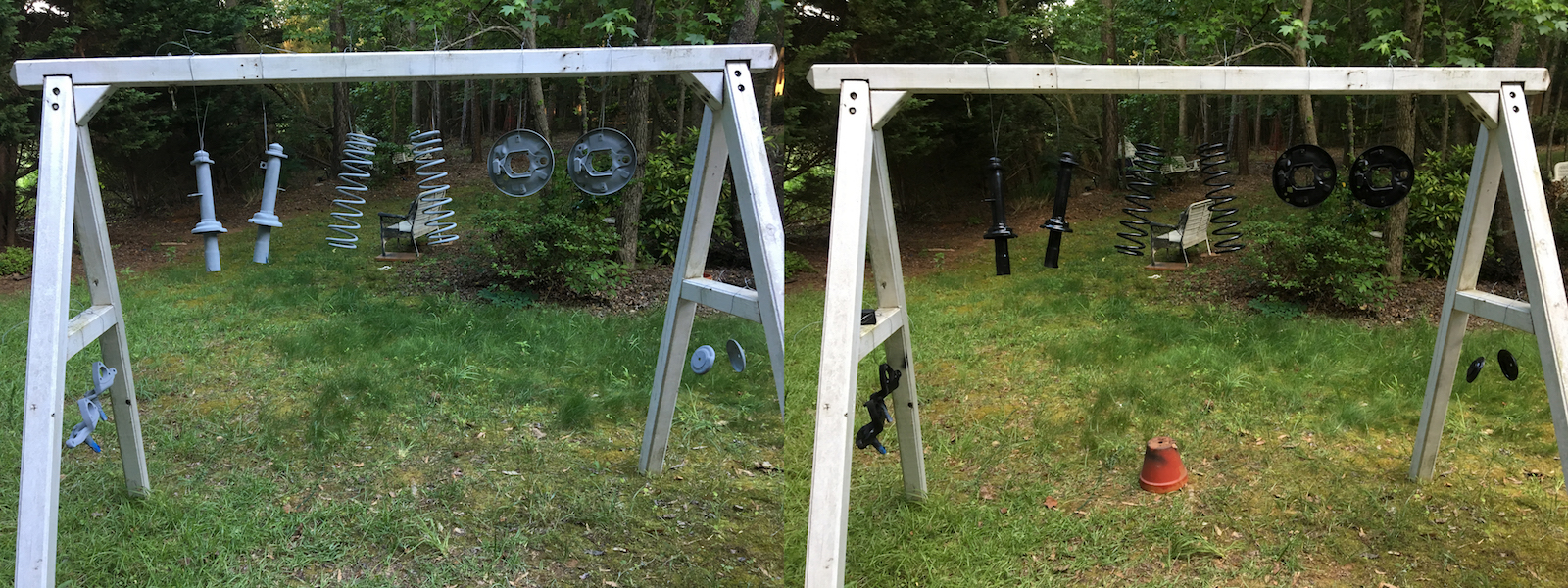
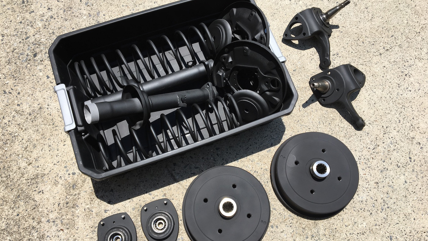
repainting everything
I took all of the brake and suspension parts to a local sandblaster and had them taken back down to the bare metal. This can be done by hand, but it's a time consuming process and some small nooks and crannies are impossible to get to with a wire brush. I got all of these parts sandblasted in under an hour and it only cost about fifty dollars. I mounted them all on this swing trestle we have sitting in our backyard and painted them all with the cheap basic matte black Rust-Oleum paint, which I have had really great results with.
I also painted the new rear brake drums in a high-temp black grill paint, cleaning them thoroughly with brake cleaner and degreaser. My dad also cleaned up the strut bearings and I repainted them as well. I had decided last minute to upgrade to disc brakes in the front, so I painted the calipers as well.
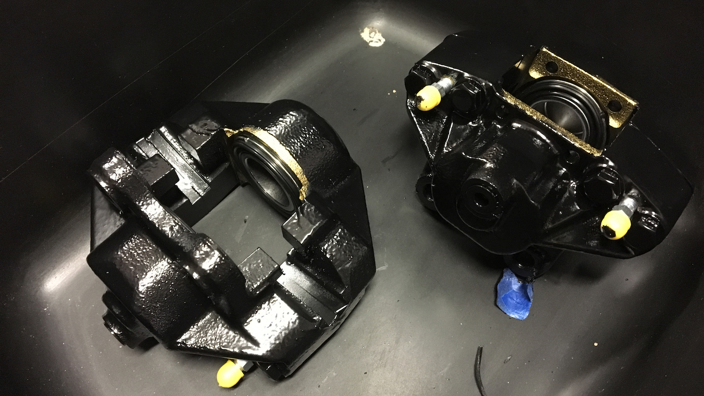
reinstalling struts, disc brakes
The struts were installed back in the strut towers and clamped in with the clamping ring. My dad and I actually fabricated a custom face spanner with some c-channel and two nuts ground square to tighten these. I installed new ball joints as well. I don't have many pictures from the rest of the installation process as it was a two person job. My dad and I compressed the springs onto the strut towers and secured the strut tower into the ball joint (along with the steering knuckle) and the strut tower bearing as described in the Bently repair manual. I replaced the strut dust cover and rubber stops with new ones from JBugs.
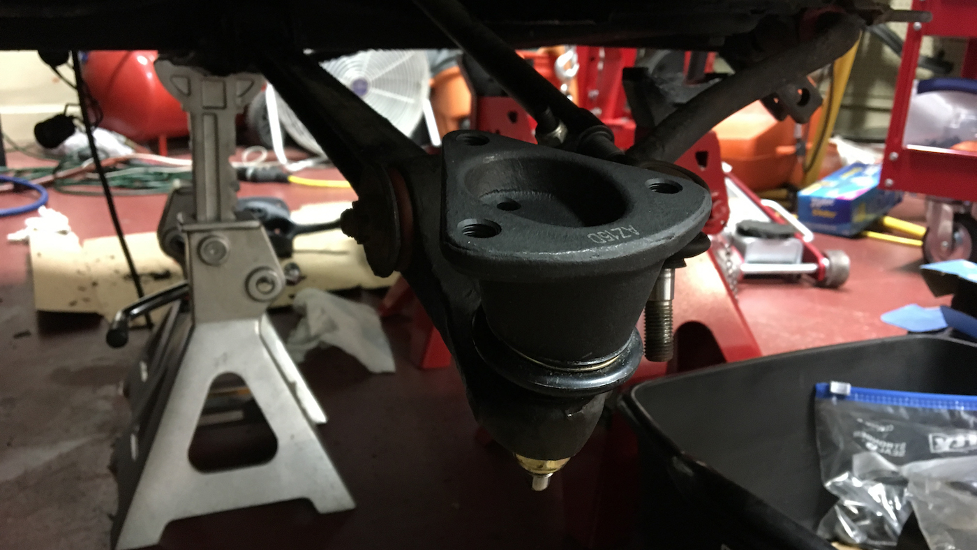
The disc brake calipers mount onto brackets that take the place of the old drum brake backing plates. I installed these, installed new wheel bearings into the discs, mounted the discs onto the front spindles, mounted the calipers and installed the brake shoes. I also replaced the soft lines in the front, and routed new hard lines from the soft lines to the calipers. I'm pretty proud of my routing.
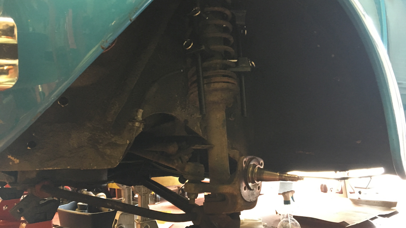
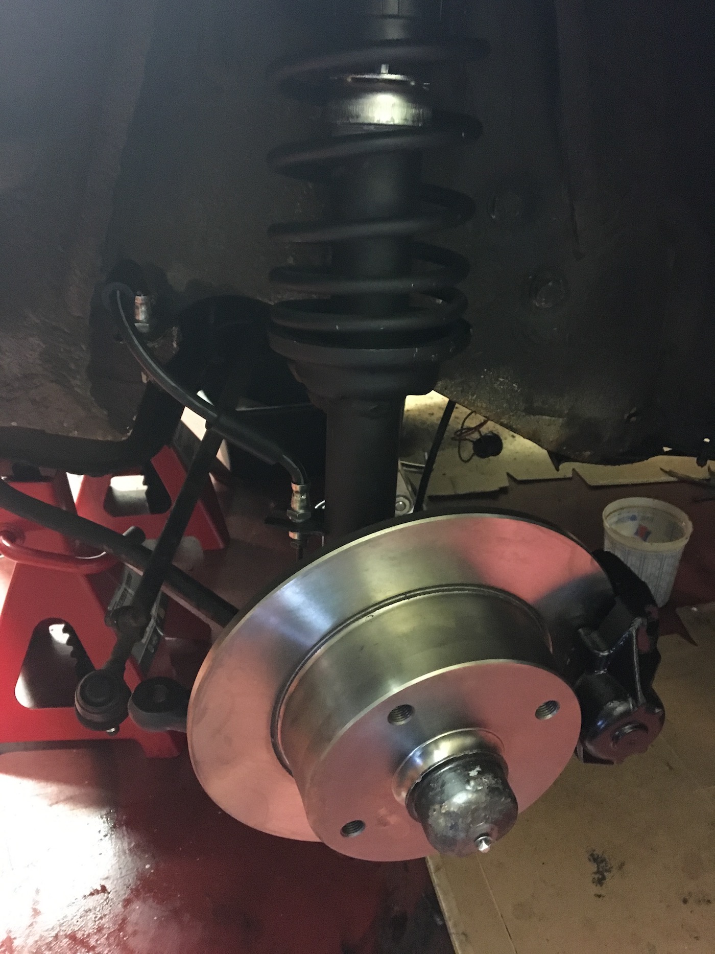
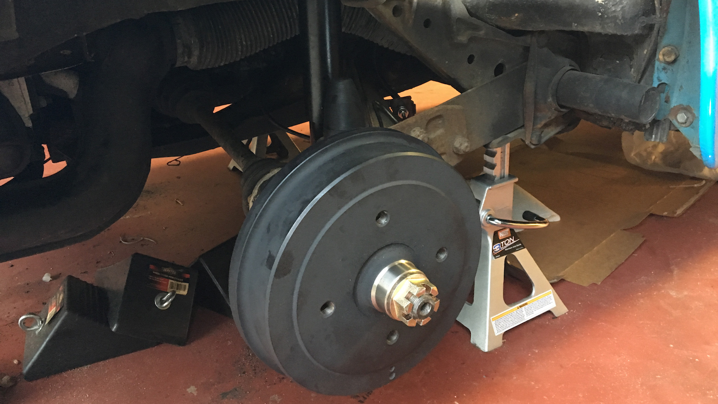
Here's an overview of all of the work done on the front suspension and brakes, just before the wheel went on (don't worry, I connected the steering linkage).
rear shock installation
At a recommendation from (Clyde)[https://clydesaircooled.com/] I used a piece of threaded rod with some nuts to stretch out the lower rear shock mounts back to the correct shape. It worked incredibly well. Installation of the shocks was as easy as removal, just two bolts.
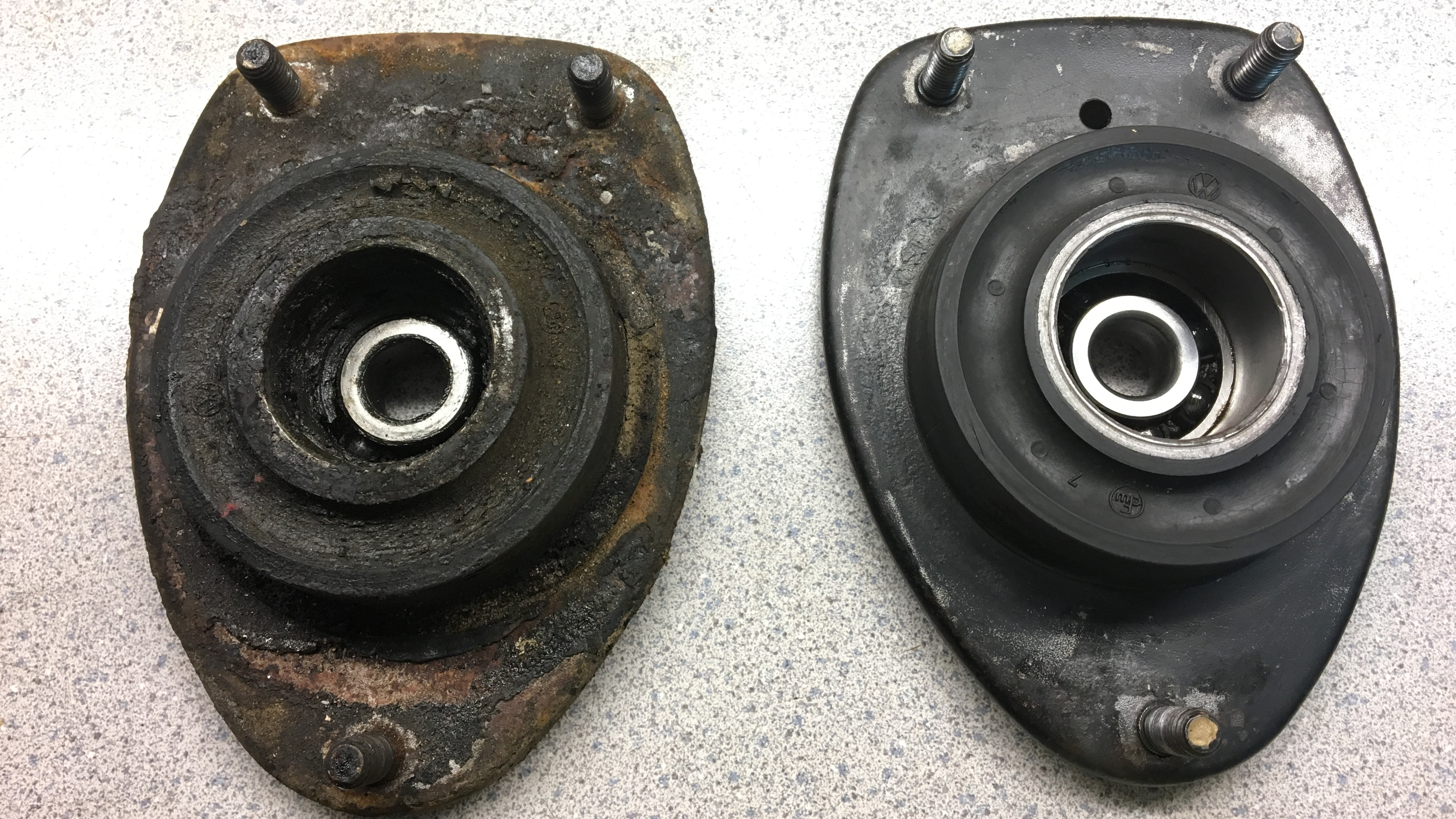
rear brake rebuild
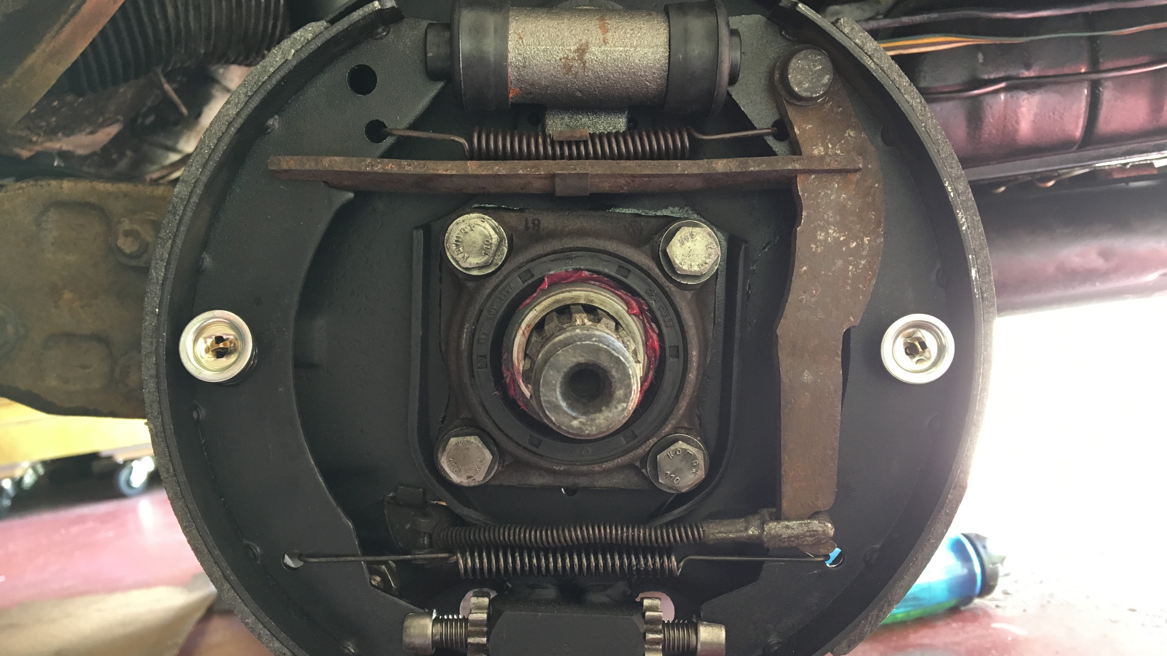
I reinstalled the backing plates in the rear, adding some Permatex aviation gasket maker (No.3, the same stuff I used to join my engine case halves) between the swing arm and the backing plate, and between the backing plate and the bearing cover. There should be gaskets here, but they weren't there when I took the backing plate and bearing cover plate off. I had seen a few people online use gasket maker with no problems, so I went with it. I added some extra bearing grease to the inside of the bearing cover. I installed new slave cylinders, new pads, and new springs and pins.
It's probably about time for a rebuild of the CV joints and rear bearings, but I decided to leave that to another day.
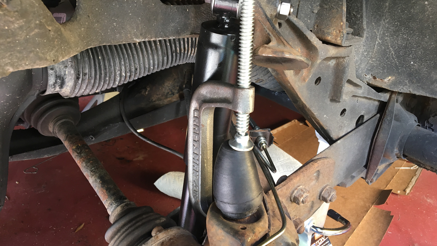
routing rear brake lines, installing suspension stops
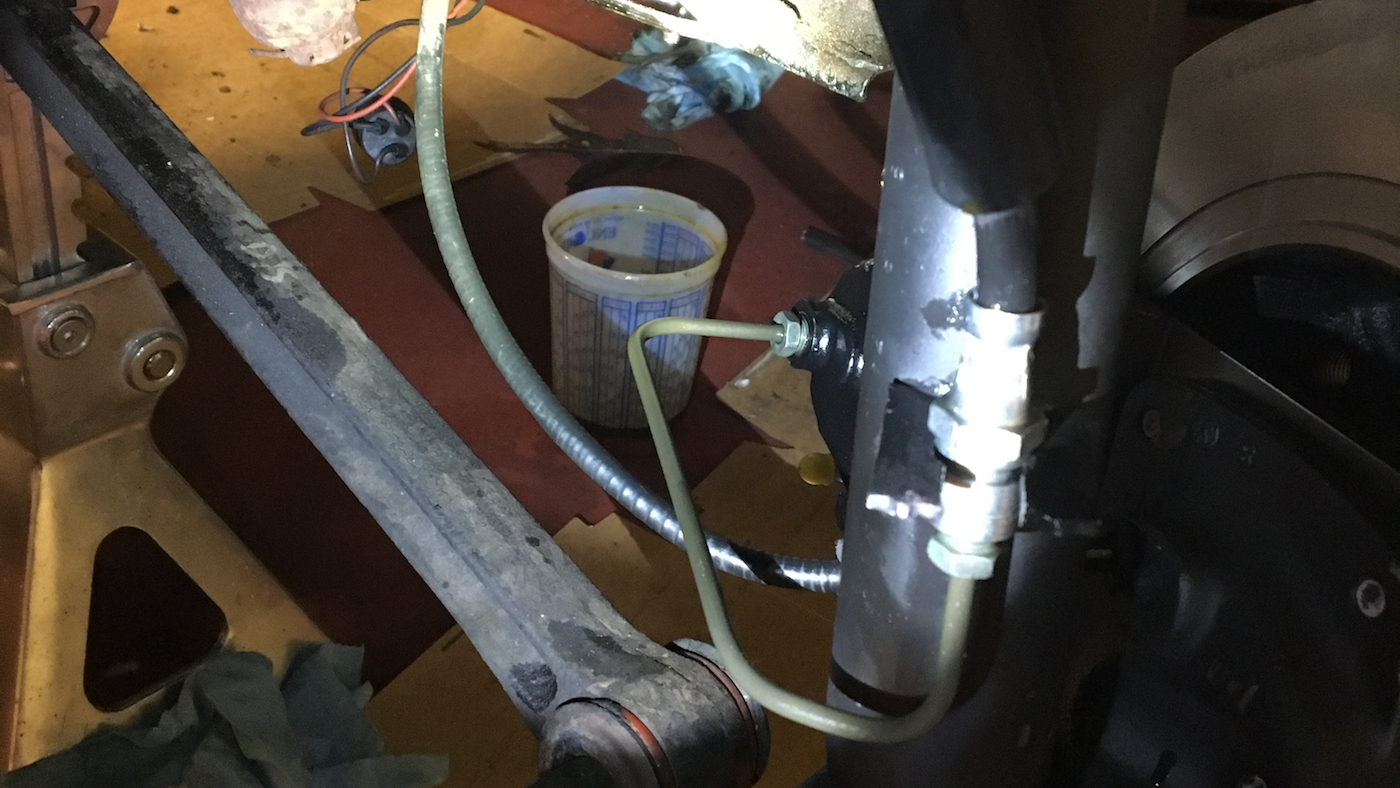
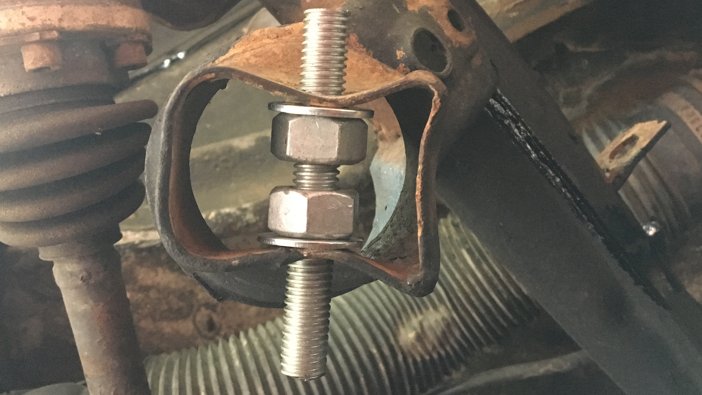
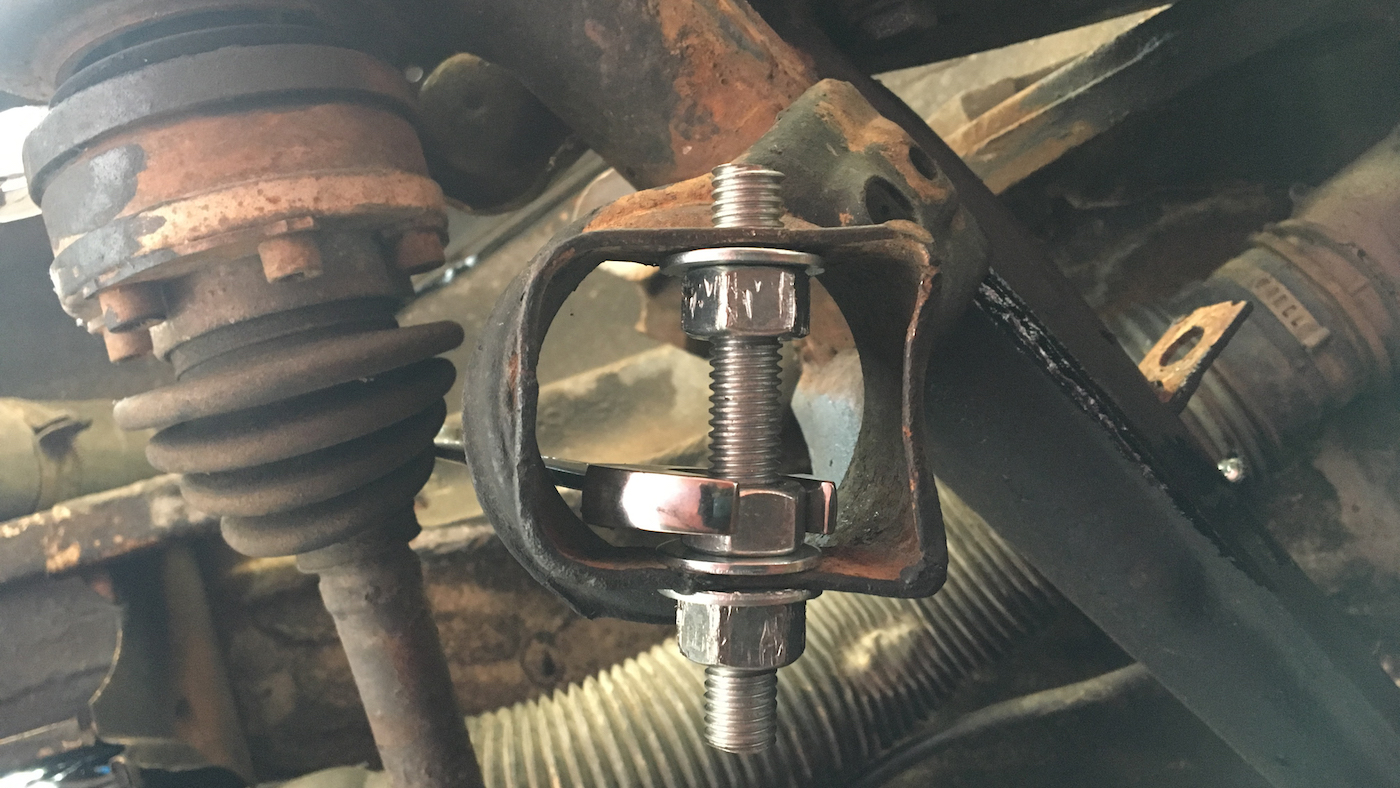
I installed new soft lines in the rear as well as new hard lines from the soft lines to the slave cylinders (I actually replaced every hard brake line in the car except for the hard line that goes across the top of the transmission and the hard line that goes from the drivers side to the passengers side in the front). I also installed new suspension stops in the rear as the existing ones were falling apart being held together with bits of wire. I tried my hardest to get these on by hand but was having no luck. I came up with this way of compressing them on using a c-clamp. I put a bit of lithium grease on the metal nub to make the rubber slide easier over it.
You can also see the routing of the new hard line in the rear.
finishing up
It took a while to bleed all of the air out of the lines and adjust the drums correctly. After bleeding all of the air out of the system the brakes were orders of magnitude better than they have ever been. However, the most rewarding part of the work was probably the improved ride quality. It was night and day. The car handles much better than ever before and going over potholes around Atlanta is almost an enjoyable experience now.
I think that about wraps things up.
05/10/2017
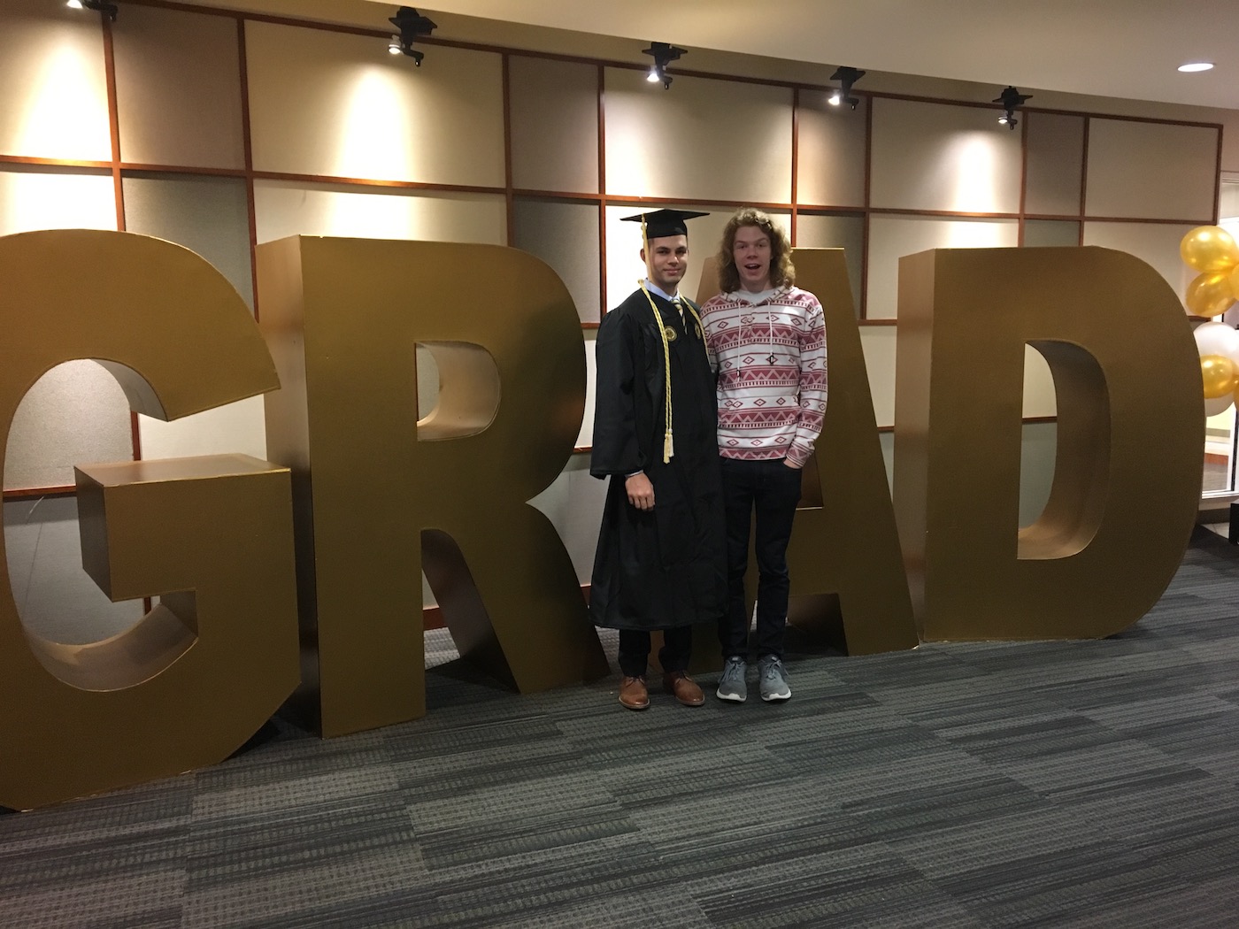
graduated!
Just thought I'd share this photo I got with my brother.