07/20/2015
electronic business card | pt. 2
I've spent the last month developing the prototype. I got my boards in from OSHPark a few days ago, put one together in the lab after work and got the main function of displaying a message up and working. I'll cover the development and debugging process here.
component selection and circuit design
For the microcontroller, I picked a Microchip PIC18F2XK20. I paired it with an LIS3DH 3-axis, adjustable-range (up to ±16G) accelerometer from STMicroelectronics. The adjustable range ensured that, if I had gotten my napkin acceleration calculations wrong (as to how much acceleration the board will experience when shaken), I would still have some range to sense the motion of the card. The power comes from two CR2032 coin cells in basic SMD friction-mount battery holders. These should have enough capacity to power the card for a full hour or more of shaking (again, if my napkin calculations are correct). Since I'm not using any fancy constant-current LED drivers, and instead using resistive current limiting, I wanted to ensure that the components had a consistent operating voltage independent of the battery voltage (which will drop over the remaining charge of the cells), and for this I used a MCP1640 step-up boost converter.
Choosing components was somewhat difficult. I anticipated the final construction of the card to be a stackup of a 0.6mm PCB to hold the components, with a 1.0mm thick material stacked on top, with holes in the top layer to allow for the components on the bottom to "stick up" through the top layer. This stackup of materials gives a final thickness of 1.6mm, which would allow me to use CR2016 (20mm diameter, 1.6mm thick) batteries in the final version. These batteries can be purchased in a tab-mount package, which could be soldered onto the 0.6mm PCB and "stick up" through both layers in the stackup. -- This means that any part I use needs to be 1.0mm or thinner. Oftentimes I would find a component that was perfect in all regards, except for the package height. Of course, I could have chosen taller components for this prototype, but I didn't want to repeat the entire design process when I needed to pick thinner parts.
This endeavor gave me a lot of respect for the Coin, which is an electronic credit card with an overall thickness of 0.8mm, half as thick as what I am attempting to build. Their product uses thin-film lithium batteries, a (likely) custom E-Ink display, and some sort of flexible PCB with chip-on-board construction. Their entire package is then somehow cast into a piece of injection molded plastic. -- I've concluded that without an exponentially larger sum of money, such technology is simply out of DIY'er monetary reach (for now).
When picking the microcontroller, I made sure I had enough I/O to drive 10 LEDs (tall enough a column to allow for some different font options). I made sure it had at least one wake-on-interrupt pin. The accelerometer has an internal state machine that allows for the execution of small "programs." These can still be run in the low power, low sample rate mode, and can allow me to put the uC to sleep if the user doesn't shake it for a while and then wake on an acceleration that is large enough. This will keep the batteries alive longer if the user forgets to turn the power switch off after use. The uC also needed at least one ADC peripheral for the ambient light sensor (ALS) I placed on board (read more about the motivation behind this in the previous post). -- I decided to go with an ALS IC instead of other options due to the small amount of external circuitry required. The only consideration here was to make sure that the response time was low enough to allow it to sense rapid changes in ambient light. -- I also made sure there was an extra UART peripheral which would allow for easy debugging during board bringup.
I could have picked a lower-range PIC, I certainly don't need the amount of flash or the processing power that this PIC18 will provide, but again, since I'm hoping this is a bit of a hackable platform, I wanted to have more than just the minimum amount of power needed. I also could have chosen a different package with a smaller pin count. Three pins are used for the ICSP programming header, which don't have to be dedicated only to programming, but it gets a little hairy when trying to use them as I/O, and I wanted to avoid having to do this. I had an extra interrupt-enabled pin and was able to connect both interrupt outputs of the accelerometer to the microcontroller, which is probably not needed. Lastly, the UART for debugging was excessive (though again, consistent with the spirit of hackability).
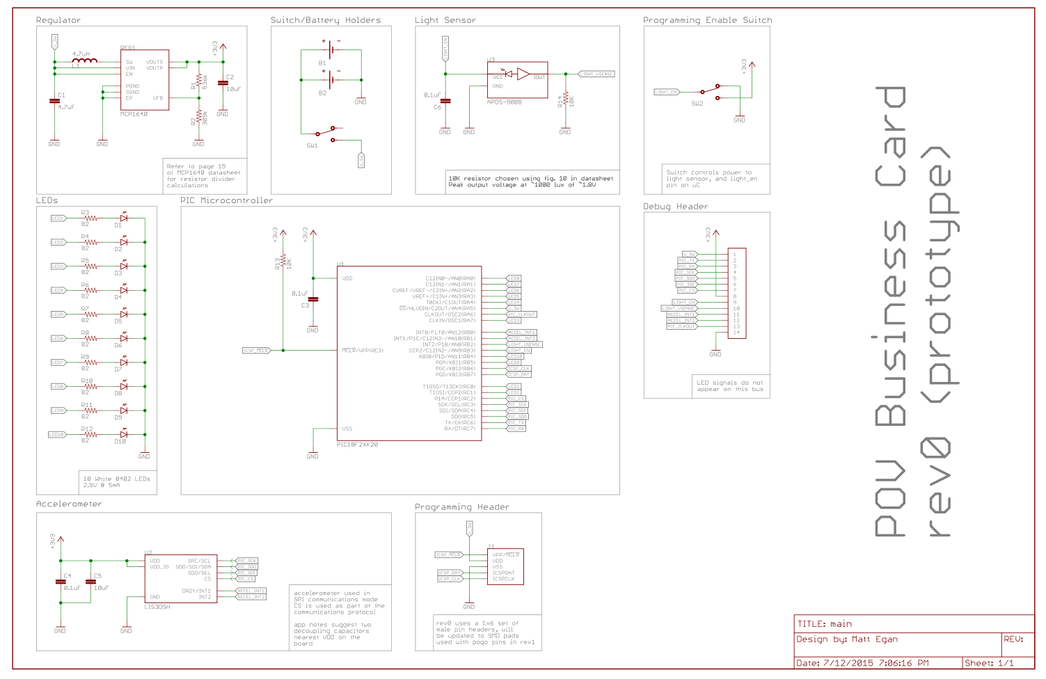
The schematic is largely uninteresting. The only slightly interesting bit would be powering the ALS from a second toggle switch, which also asserts an I/O pin on the microcontroller, signifying that the user wishes to program a new configuration into the board.
board layout
This is the first board I've routed to completion. I've started a few other designs in the past but never completed them. This whole process took a little longer than I would have liked, mainly because I insisted on creating all of my own symbols and packages. While you can find libraries online for eagle that contain all of the parts I used, I wanted to make sure all of the silkscreen and footprint design was consistent, and it was faster to repeat all of the work myself then go in and modify existing work. As an added bonus, I now have an Eagle library I can call my own and fully trust. I took a while to be conscious of how I was naming footprints and packages, and some nights I sat and spun my wheels because I couldn't figure out how I wanted to name a part.
I tried routing the subsections of the board as tight as possible, as practice for the second revision where I want to fit the components into the smallest possible area. Especially difficult was the placement of the components around the boost converter. I also tried making the traces as clean as possible, something eagle makes a bit difficult. The follow-me routing is almost unusable and thus I did not use it. If I happened to place five traces next to one another, only to find that the sixth would not fit in the available space, I had to rip up the sections of the first five, move them slightly and then place the sixth trace. Also, I wanted to make sure I was using consistent 45 degree angles on every bend, something that was a bit difficult to do while routing between different grid sizes.
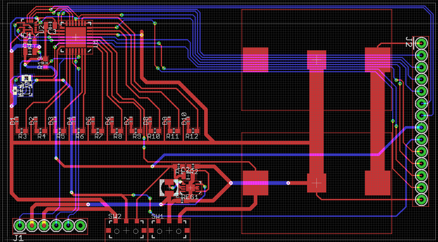
Here's the finished 2-side board layout. The large through-hole section on the right of the board is the debug connector. It breaks out a lot of the signals so I can probe on them to make sure stuff is working. One mistake in the layout was not rounding the corners slightly in the outline layer. This led to some sharp corners on the board. I added holes in the bottom, opposite of the LEDs as I thought I might try and see if I can swing it from some string to generate patterns as well.
board assembly and some interesting bringup issues
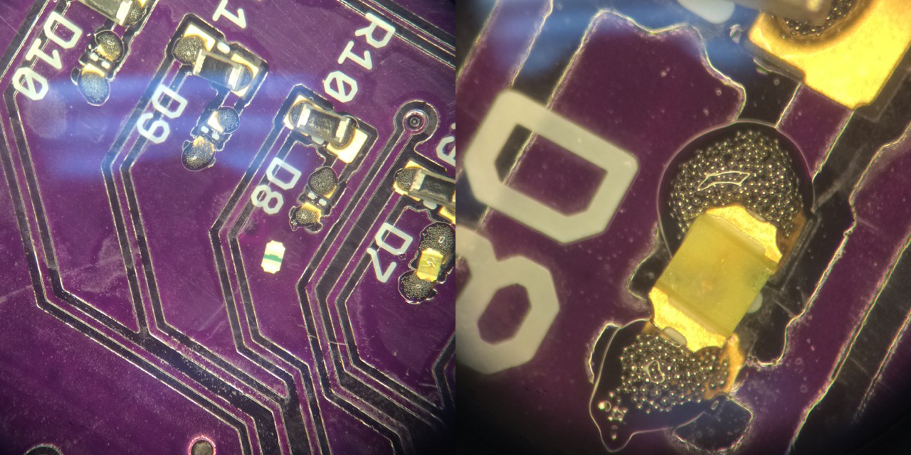
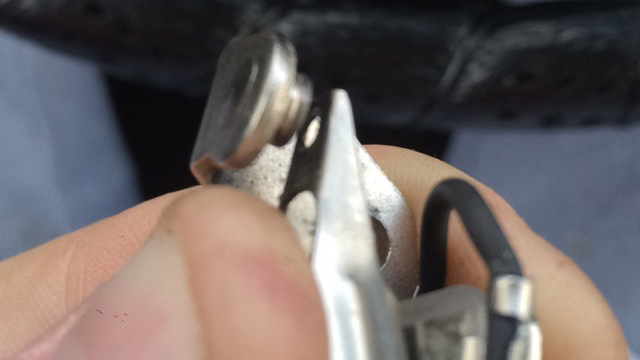
This was also the first surface mount board I have assembled. It was made somewhat painless by a microscope and hot air station in a lab at my internship I managed to get some time on. Most painful were the tiny 0402 LEDs. The polarity marking was on the bottom, so I had to flip them over, check the polarity mark, and then very carefully flip them over making sure they didn't fly out of my tweezers in the process (it also didn't help that not a single pair of tweezers in the lab had unbent tips). I eventually just noted the configuration of the bond wires to the die itself which I could see through the clear package. I used the hot air on the board in stages, which was fairly easy because the board had small groupings of components.
The first issue I ran into was not ordering the boost converter. -- Searching the schematic for a potential workaround, I noted that the VDD connection on the programming port was connected to the output of the on/off switch, meaning that when the switch was in the on position then the VDD pin on the programming port would have the battery voltage on it. This design decision was made such that, when the switch is in the off position, and the board is powered through the programmer, the programmer supply is not also across the batteries. However, since the boost converter is only on the board to create a stable 3.3V supply, and everything on the board will work down to the 3V the batteries supply, I could simply jump this VDD pin on the programming port to the regulator output pin. This powers the board off the batteries directly, and still allows me to use the switch to turn the board on and off until the the boost converters arrive in the mail.
After the entire board was assembled, I wrote a small program to turn all of the LEDs on the board on. Although the programmer could talk to the PIC and the program would upload, not all of the LEDs seemed to turn on. I could turn different ones on, but as soon as I modified the program to turn all of the LEDs on, the board would turn off. At first I figured that I had placed too much solder paste on the board and shorted some pins together under the PIC or the LEDs and I was creating a short through the PIC by attempting to turn specific LEDs on. To fix this, I soldered a new PIC onto the board, but was still getting the same issues.
Scratching my head at this point, I started inspecting the board carefully under the microscope, looking for any soldering issues. Doing this, I accidentally discovered that when held under the microscope (which had a very bright ring light) the board would power down. I first thought that this might be the ALS drawing too much current (it acts as a current source, drawing more current from the supply the more light it is illuminated with) causing the battery voltage to droop below 3V, so I covered the ALS with some black electrical tape and held the board under the microscope again, only for it to have the same effect. -- Feeling defeated, I decided to give the schematic one overview for any potential issues, which is when I noticed that one of the LEDs was on an I/O pin that could also function as the PIC's low voltage programming pin. Thinking this might be an issue, I re-checked the PIC configuration #pragma config lines, to discover that had not disabled low-voltage programming.
PICs come from the factory with low voltage programming enabled. Since low voltage programming does not preclude the standard programming voltages, and if your manufacturing process depends on low voltage programming, it would be impractical to have to use the regular programming voltage to enable the low-voltage programming mode.
With the one configuration line changed the board no longer powered off after being illuminated with bright light, and I was able to turn all of the LEDs on in code. My theory at the moment is that, there was a small amount of photogeneration (basically the LED acting as a PV cell) in the LED, creating a high enough voltage across the series resistor to trigger the low voltage programming mode. -- Also, it seems that if the PIC is in low voltage programming mode then it will happily put itself into programming mode if the I/O pin is brought high in software.
more board bringup
The next most important thing to check that was working was the accelerometer. The first thing I did was write some code to enable the serial port on the PIC so that I could get some data off of it to analyze. I don't really like using any libraries provided by Microchip, so I just wrote a few functions to setup the USART peripheral, and some small utility functions. Modeling the Processing approach, I like to have a setup() function that runs at the beginning of main() and calls out to other setup functions in the appropriate order.
Setting up the UART (and anything really on a microcontroller) is really just an exercise in reading the datasheet and putting 0's and 1's in all of the right memory locations. Since most of the mnemonics for the registers are sometimes impossible to remember, I like to leave comments as to why something was set to say, the value 8. Always helps down the road.
void setupUART() {
    //set the baud rate to 115.2k, using Fosc = 64MHz, the value for SPBRG is
    //taken from the datasheet
    SPBRG = 8;
    SPBRGH = 0;

    //configure the TX and RX pins as outputs (the EUSART will reconfigure them
    //automatically
    TRISCbits.TRISC6 = 1;
    TRISCbits.TRISC7 = 1;

    //configure the EUSART in async mode
    TXSTAbits.SYNC = 0;

    //enable the serial port, and enable transmission
    RCSTAbits.SPEN = 1;
    TXSTAbits.TXEN = 1;
}
From here, I wrote some simple functions to write out a character array byte by byte, and also a function to convert from integer to a character array (no printf here).
void UARTPutStr(unsigned const char *data) {
    while(*data != '\0') {
        UARTPutC(*data);
        *data++;
    }
}

char *intToStr(int num) {
    static char out[7]; //INT_MIN = -32768, so we'll need at maximum 6
                        //chars and a null termination to represent an integer
    char digits[6];     //a place to store the digits
    int digitIndex = 0; //keep track of where in the digits array we're placing
                        //digits

    int offset = 0;
    if(num < 0) {
        out[offset++] = '-';
        num = num * -1;
    }

    do {
        digits[digitIndex++] = (num % 10) + '0';
        num /= 10;
    } while(num);

    for(int i = 0; i < digitIndex + offset; i++) {
        out[i + offset] = digits[digitIndex - i - 1];
    }
    out[digitIndex + offset] = '\0';
    return out;
}
Some frustration came when attempting to read data from the accelerometer. Following the datasheet's recommendations, I configured some accelerometer registers to enable continuous block updates, set the update rate to 100Hz, enable an antialiasing filter with an 800Hz bandwidth (to reduce noise, basically a low pass filter), disabled self test, enabled 4-wire SPI mode, and set the scale to ±16G. However, the data from the accelerometer was always the same value, even when the board was violently shaken. Lots of head scratching ensued until I found an application note from ST noting that the axes are all disabled after startup. The datasheet lists the X, Y and Z enable register bits as "enabled at POR" so I figured they should be initialized after the accelerometer is powered on. However, the initialization sequence that is detailed in an application note states that the accelerometer powers up with all axes initially enabled, reads some calibration memory, does a self-calibration, and then disables all axes by modifying the appropriate register. So, while the datasheet is technically correct that at reset the axes are enabled, after the initialization sequence is completed they are not enabled. To fix this, I just had to set the enable bits to the correct value, which was simple enough. -- Again I wrote some routines to abstract away SPI operations, and then wrote a setup function for the accelerometer.
void SPIRead(unsigned char addr, int length, unsigned char *out) {
    //bring CS low to begin the cycle
    LATCbits.LATC2 = 0;

    //load and tx the address into the SPI output buffer, with the read flag set
    //[7] is the R/W bit (1 -> read), and [6:0] are the address bits
    SSPBUF = addr | 0b10000000;
    while(!SSPSTATbits.BF);

    for(int i = 0; i < length; i++) {
        //write out dummy data to clock the device
        SSPBUF = 0xFF;
        while(!SSPSTATbits.BF);
        out[i] = SSPBUF;
    }
    //bring CS high to end the cycle
    LATCbits.LATC2 = 1;
}

void SPIWrite(unsigned char addr, int length, unsigned char *in) {
    //bring CS low to begin the cycle
    LATCbits.LATC2 = 0;

    //load the address into the SPI output buffer, with the write flag set
    //[7] is the write bit (0 -> write), and [6:0] are the address bits
    //chop off the 7th bit of the address if it was set for some reason
    SSPBUF = addr & 0b01111111;
    while(!SSPSTATbits.BF);

    for(int i = 0; i < length; i++) {
        SSPBUF = in[i];
        while(!SSPSTATbits.BF);
    }

    LATCbits.LATC2 = 1;
}
void setupAccelerometer() {
    unsigned char data[2] = {
        0b01100111,     //data rate -> 100Hz (ODR = 0b0110)
                        //block update -> continuous (BDU -> 0b1)
                        //axis enable -> X, Y, Z enabled
        0b00100000      //AA filter bandwidth -> 800Hz (BW -> 0b00)
                        //scale selection -> +-16Oh G (FSCALE -> 0b011);
                        //self test disabled (ST -> 0b00)
                        //SPI mode -> 4 wire mode (SIM -> 0);
    };
    SPIWrite(0x20, 1, &data[0]);
    SPIWrite(0x24, 1, &data[1]);
}
Then, since the Y acceleration is really all I'm interested in (it's the one that's parallel with the motion of the card when shaken), I wrote a function to abstract that away too.
signed int getYAcceleration() {
    unsigned char yData[2];

    //TODO : optimize this to use the automatic address increment feature
    //       of the accelerometer's SPI interface
    SPIRead(0x2B, 1, &yData[0]);    //read the MSB 8 bits of the Y axis
    SPIRead(0x2A, 1, &yData[1]);    //read the LSB 8 bits of the Y axis

    return (yData[0] << 8) | yData[1];
}
At this point, I wanted to test my assumptions about what the acceleration would look like, as well as confirm that I was going to get a semblance of something that was periodic to actually use to time when to light the LEDs up. I wrote some code to stream the acceleration readings over the serial port. Running this code, I shook the card back and forth, collected the data, and plotted it. Here are the results of one of those tests.
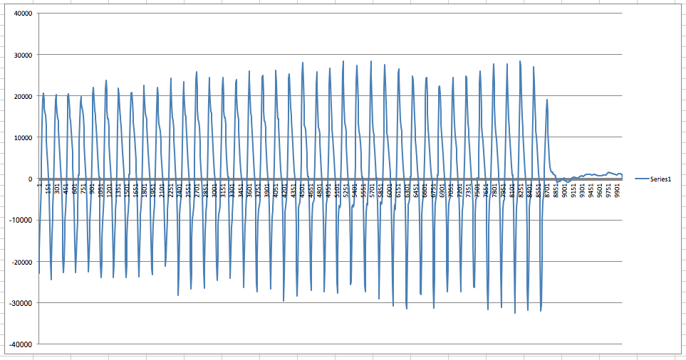
As you can see, the periodicity is easily visible, and at this point I was pretty confident that I was going to be able to make this thing work.
using the data / timer-counter magic
Interpreting the data is a little confusing. Since the data is acceleration, not velocity or position, an initial thought would be to numerically integrate the data twice, and then use the resulting data as the position data. However, the arc the hand makes when shaking the card will have the "zero crossing" of the acceleration in the middle of the arc, it's when the hand goes from "speeding up" to "slowing down" so the acceleration should cross from positive to negative, or negative to positive, the acceleration should reach a maximum at the edges of the arc, when the direction change occurs, after which the acceleration should start to decrease in magnitude again before crossing zero again.
Mathematically, if the position is considered to be sin(t) (considering the motion as linear) then the second derivative in time will be the acceleration (which is what the accelerometer reports), which will be -sin(t). Thus, the zero crossing of position occurs at the same time as the zero crossing in acceleration as predicted. The peaks occur also at the same time, just opposite in sign. Thus, it's possible to treat the acceleration data as just negated position data (in this case).
Note that this is the acceleration in the direction of the linear velocity of the board. There will also be a perpendicular component that is also sinusoidal, which could also be used. I may look at combining the two in the future to reduce noise.
The end goal is to distribute the "rows" of the text or graphic that needs to be displayed when the card is shaken over this arc. To do this, I used two timers. One timer, running at a slower frequency, is used to measure the time between subsequent "peaks" and "troughs" in the acceleration. This time is then divided by however many columns need to be displayed, and a second timer is used to count these intervals, increment the column to display when required, and turn the LEDs on and off according to which column is currently being displayed. With that said, here's the code that searches for the peaks and troughs, and then sets some variables up for the timer interrupts to use.
int main(int argc, char** argv) {

    setup();

    //enable interrupts
    INTCONbits.GIE = 1;     //enable global interrupts
    INTCONbits.PEIE = 1;    //enable peripheral interrupts

    //setup timer 0, which times the length of one shake
    T0CONbits.T0CS = 0;     //timer 0 is driven by Fosc/4
    T0CONbits.PSA = 0;      //enable timer 0 clock prescaler

    T0CONbits.TMR0ON = 1;   //turn timer 0 on
    T0CONbits.T0PS = 0b010; //1:8 prescale value for timer 0;

    //INFO : timer 0 will overflow at 7.813KHz, meaning that one overflow of periodCount is equal to
    //       128us
    INTCONbits.TMR0IE = 1;  //enable timer 0 overflow interrupts

    //setup timer 1, which times out each column of the display
    T1CONbits.TMR1ON = 1;   //turn on timer 1
    TMR1H = 0xF0;           //set the count to 15/16ths of the overflow value
    TMR1L = 0x00;

    //INFO : since timer 1 is configured with a prescaler of 1:1, and Fosc/4 = 16MHz, it will
    //       overflow (16bits) at 244.1Hz, with a period of 4.096ms, to cause the overflow to occur
    //       faster, the counter register is preloaded with 0xF000 at every overflow, which is
    //       15/16ths the overflow value of 0xFFFF, so the counter (running at 16Mhz) only has to
    //       count 0xFFF more to overflow, this will happen at 3.907kHz, or every 256us, this is
    //       chosen so that if there are about 3 shakes in a second, the timer can still keep track
    //       of line widths of 100 or more


    signed int y;
    signed int previousY = getYAcceleration();
    float shakePeriod;
    float columnPeriod;

    while(1) {

        //get the current y acceleration
        y = getYAcceleration();

        //need to do a peak find, alternating between "peaks" and "troughs"
        //alternating between searching for these get us the left and right
        //edges of the shake
        if(posPeak && y < previousY || !posPeak && y > previousY) {
            if(posPeak && (y > THRESHOLD) || !posPeak && y < -THRESHOLD) {
                //a peak was found, now we need to search for the opposite peak
                posPeak = !posPeak;

                //now we need to setup timer 1 to generate `rowCount` pulses during one shake
                shakePeriod = periodCount * 128.0e-6;
                columnPeriod = shakePeriod/((float)columnCount);
                columnTimerPeriod = (int)(columnPeriod/(256.0e-6));

                //enable TMR1 interrupts
                PIE1bits.TMR1IE = 1;

                //start a new period
                periodCount = 0;
                columnTimerCount = 0;
                currentColumn = 0;
            }
        }
        previousY = y;
    }
}
This code first sets up two hardware timers. Timer0 is used to time the period of the acceleration "sine" wave. It's clock source and prescale value cause it to overflow and generate an interrupt at 7.813kHz. Timer1 is setup similarly, but because it is a 16 bit timer, every time the timer overflows it is reset with a value of 0xF000, to increase the frequency at which the timer overflows to around 4kHz.
In the main loop, a positive or negative peak is found by examining the current and past acceleration value, and toggling between looking for a peak and a trough ("negative" peak value). periodCount is the number of Timer0 interrupts that have occurred (it is incremented in the interrupt), this is multiplied by the period of the interrupt to get the total time since the last peak or trough. This time is then divided by how many columns need to be displayed, and then this value is then divided by the period of the "column" Timer1 interrupts. The resulting value is how many Timer1 interrupts should occur between changing the column of LEDs to the next value. The interrupt, shown below, handles this.
void interrupt isr(void) {
    if(INTCONbits.TMR0IF) {
        //this timer increments a period timer so we can count how long the last shake took
        periodCount++;
        INTCONbits.TMR0IF = 0;
    }
    if(PIR1bits.TMR1IF) {
        TMR1H = 0xF0;
        TMR1L = 0x00;
        if(columnTimerCount >= columnTimerPeriod) {
            currentColumn++;
            if(currentColumn > columnCount) {
                setLEDOutput(0b0000000000);
            } else {
                if(posPeak) {
                    setLEDOutput(image[columnCount - currentColumn - 1]);
                } else {
                    setLEDOutput(image[currentColumn]);
                }
            }
            columnTimerCount = 0;
        } else {
            columnTimerCount++;
        }
        PIR1bits.TMR1IF = 0;
    }
}
setLEDOutput is a short, unglamorous function that takes a 10 bit wide binary value and sets the status of the LEDs. The image buffer is an array of 10 bit wide values. Otherwise, this should be pretty self explanitory. The only tricky bit is figuring out if the card is moving "forwards" or "backwards" and subsequently traversing forwards through the image buffer or backwards.
static unsigned int image[XXX] = {
    0b0001111111,
    0b0000000010,
    0b0000001100,
    0b0000000010,
    0b0001111111,
    0b0000000000,
    ...
}
demo
Here's a clip of when I first got it working. Keep in mind, it looks a lot better in person, due to the aliasing the frame rate of the video causes.
generating the image buffer
Typing out 100 or so 10 bit wide fields is not a great way to spend an afternoon, so I wrote a quick script in Node.js using the aptly-named get-pixels library to take 10 pixel tall black and white image and convert it to something I could copy and paste into my code.

var getPixels = require('get-pixels');

getPixels("mattegan.png", function(err, pixels) {
    if(err) {
        console.log(err);
    } else {
        var w = 59;
        var h = 10;
        var lineStr;
        var pixels = pixels.data;
        for(var col = 0; col < w; col++) {
            lineStr = '\t0b';
            for(var row = 9; row >= 0; row--) {
                var pixelStartIndex = (col + row * w) * 4;
                var color;
                for(var c = 0; c < 3; c++) {
                    color = pixels[pixelStartIndex + c] << ((2 - c) * 8);
                }
                lineStr += color == 0 ? '1' : '0';
            }
            console.log(lineStr + ',');
        }
    }
})
conclusion
I'm going to focus a bit on the software now I think. I would like to clean it up and maybe use some more complex methods for ascertaining the motion of the card. I also need to try and get the "serial via light" working, as well as the low power modes. However, I would like to get working on the second revision of the hardware, a more "polished" and presentable version. This whole thing has been a lot of fun and a super valuable learning experience, and I'm excited to see where else it takes me.
06/25/2015
electronic business card | pt. 1
The career fairs at Georgia Tech are pretty cutthroat. The main fair during the Fall semester is attended by over 200 companies and a large portion of the twenty thousand students who attend GT. Safe to say, standing out is difficult. I didn't have much luck this past year, and I kind of had to go with anyone who would offer me a position, so I'm looking to step my game up this round. I've decided to create an electronic business card.
market research / a summary
Plenty of people have done PCB business cards in the past, so there's even some challenge standing out from the prior art. It seems the most popular designs merely blink some LEDs activated by a button powered by a coin cell. Creative versions will use a capacitive touchpad and a small microcontroller. Coin cell batteries use bulky holders, which make this type quite thick and thus less likely to be stored in a recruiter's wallet. These are also quite uninteresting, you don't have to take a circuits class to light up an LED, so these type don't do much to broadcast much of a skill set.
On the contrary, there are some very well done cards. This one, by Limpkin, uses two 1.0mm PCB's in a sandwich to allow the card to slot into a USB port for power. I have seen 2.0mm boards before to allow powering via USB, but the sandwich allows the components to be flush with the surface of the card, so the card is easily walletable.
Others use the USB port for power and data, the most common of these types simply enumerate themselves as a USB mass storage device with a resume already on the drive. These are pretty uninteresting to me, though from a marketing standpoint they are optimal. Assuming the card is somewhat thin there's a good chance that anyone that is given one will keep it around to use as a USB drive, increasing the exposure to your name and contact information. This is something I wanted to encourage with my ideas.
There are more interesting ones in this space. Frank Zhao's card emulates a USB keyboard, and waits for the user to open notepad and toggle caps-lock three times, after which his resume is typed out by the card into the open notepad. Ch00ftech does something similar but emulates a USB absolute-positioned mouse instead (like a graphics tablet) to draw his logo into a paint program. This one by Ramiro Veredas is just a mass storage device, however instead of mounting his SOIC package on top of the board, he mounted it through the board, reducing the overall thickness of the board considerably.
The last one that caught my eye was this persistence of vision card. It's very bulky, so it's not going to fit into any wallets, but the design is incredibly interesting and well done. It also does something interesting immediately after you hand it to them. No need to make them wait to get back to a computer at the end of the day (when they're probably tired from talking to 100s of other eager students throughout the day). When you hand someone this, you can go "here, watch" instead of "yeah! well, when you plug it into your computer... just trust me on this."
some planning
So looking into all of this, I needed to set some goals. Here they are.
It must be walletable. -- There's no point in spending so much time on something that whoever you give it to will just throw it in their bag and, if you're lucky, they'll place on a shelf somewhere. If it's compact enough to hang out in someone's pocket, you increase the chances that they take it out and show it to other people, some of whom might be their coworkers at your dream company.
It should to something that's immediately interesting. -- Immediacy of the cool is the key here. Like before, it's cool if it does something, but it's an order of magnitude cooler if the person you're showing it to doesn't have to trust you that it does something interesting.
It should have some utility. -- You want to give whoever you're giving the card to a reason to keep it in their wallet. The longer the card is in their wallet, the longer your name is in their wallet, the more likely it is that they remember your name the next time they're looking to fill a position. -- If it is a USB drive, put some extra space on the drive so it can be used to transfer files. Even if the card lights up, make it configurable.
It should be hackable. -- This is potentially just an increase to the utility. If your card is hackable, then there's a potential that whoever you give the card to wants to change what it does, or shows it to someone who wants to. There should be debug pads and programming ports readily available.
Make it open source. -- You can't forget that the card is a simply a vehicle for your expertise. Having a card that works is impressive, but if an engineer at the company can look up your board design and see how much work you put into routing the PCB or how clean, commented and well-structured your code is, then you just became that much more valuable in their eyes. In this vein, make sure the code and PCBs are clean and thoughtfully made, make it your best work.
the idea
So, I really like the persistence of vision display. It has the immediacy factor that I want. The only problem I have with it is the utility. It's really not that interesting to have a PCB that says some random guy's name when you wave it in the air. If I'm waiving my hands around like a maniac it better be for good reason. I also want to increase the hackability, theres not much more you can do with some LEDs and a tilt switch.
To fix the utility issue, I'm going to include a light sensor of some sort (photoresistor/photodiode/phototransistor/ambient light sensor IC) to allow for asynchronous serial communications over light (think, UART over light, or a series of flashes), most likely originating from a webpage. This will allow for the message that the card displays when shaken to be changed using a web browser on a phone or computer. Hopefully this will convince the user to keep the card around indefinitely, so they can display different messages for different occasions on a moment's notice, such as "Happy Birthday" or "Congratulations, you're hired Matt!".
I also want to go with a digital accelerometer instead of a tilt switch, since it will make the card more adaptable if the user wishes to modify it's behavior by hacking it. It could be turned into an adjustable brightness night-light, or a bubble level, or a number of things. It will hopefully also allow for some data processing to improve the quality of the display.
The thinness is going to be the biggest challenge. I'm not 100% sure how I'm going to solve this issue at the moment. For now, I'm going to start on a prototype (I want to have something working by the career fair, even if they're not good enough to give out by then) while keeping the thickness of the finished product in the back of my head.
06/5/2015
vw engine build
This might go down as the most stressful thing I've ever done. Finals week ended at the end of April, and my internship just started on the first of June. School kept me too busy to work on engine, especially because I didn't have a car to ride up and down from Atlanta back home where my car was. So, when school let out for the summer, I had about four weeks to go from bins of engine parts to engine, in car, 650 miles north in Baltimore, and... spoiler alert, I didn't make it.
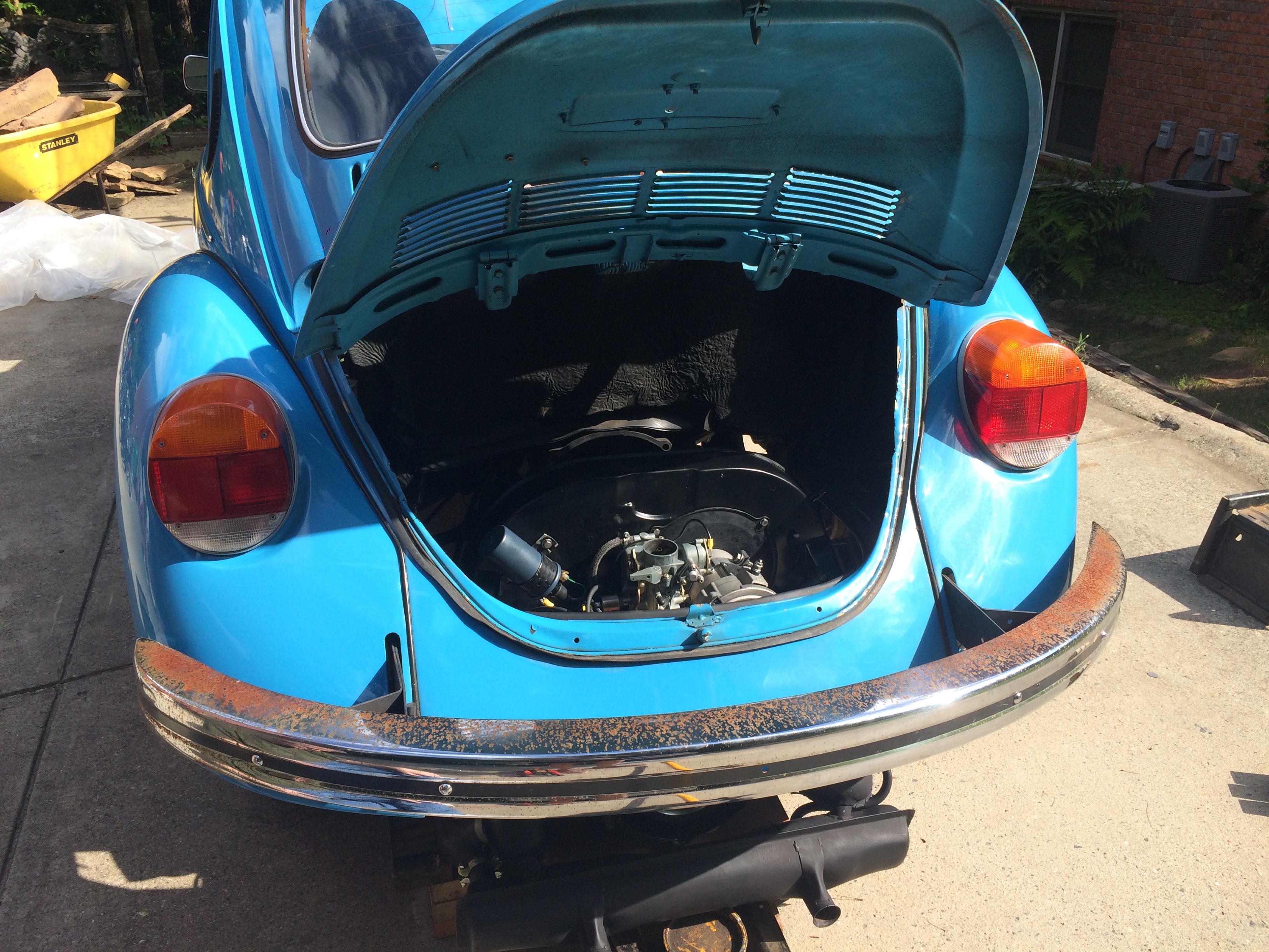
I guess I don't have any posts about why I'm having to do this in the first place. The short story is, I was in rural Virginia volunteering for a week, and one morning driving down the highway (at a fairly good clip for my little Beetle) I lost all power, I was slowing down with the pedal to the floor, which is usually not a good sign. I pulled over, and naively attempted to restart the engine, it started but was running really rough. I had no clue what was wrong, so checked the distributor (I'd had issues with low-budget caps wearing out) and it looked passable. For whatever reason I decided to pop off the rocker arm covers, and to my surprise, under the 3-4 rocker cover I uncovered a disaster. The nuts holding the rocker arm assembly to the head had backed themselves loose, allowing the pushrods to hop outside the cups in the rockers that they're normally captivated in.
I got the car towed to a garage nearby that I had access to and tried to piece it back together. The only thing I really feared was the pushrods being bent, so I rolled them on a flat surface and checked to see if they stuck anywhere. They appeared fine so I kind of put everything back together, did an oil change, and adjusted the points and timing. Standard tune up. I needed to be back in Atlanta to visit the French consulate, so I took the risk and drove it back to Atlanta. Got about an hour into the trip until things started sounding strange around Asheville. Pulled off the road and my head temps (measured with a laser temperature gun) were about 100°F too high, and the engine was running incredibly rough. I called it quits and my dad (who happened to be on a business trip nearby) had to rescue me. I came back a day or two later and picked up the car from the gas station I had to leave it at.
When I got it back to Atlanta, I did a compression check and discovered the engine had very low compression and I also found a nice clump of metal shavings in the oil strainer. So, rebuild it was. I got the engine out of the car before I left to France for a Fall semester abroad, and my car sat without an engine for the Fall and Spring semester.
The first step (which started before school was out) was to pick parts. I browsed and browsed forums and asked countless questions and read numerous articles and really just came up hands empty. People are incredibly opinionated when it comes to part selection for stuff like this, and it's especially difficult because there's really no scientific way to say that your parts combination came out better than somebody else's parts combination, especially when it comes to long term reliability. What helped me the most was Clyde, a local parts seller and friend in Athens, Georgia who supplies a lot of parts to the Volkswagen group I hang out with every once and a while. What I found is that, you really just need one very opinionated person, who only gives you one option, and who has built many engines in the past. It's impossible to get good parts advice from somebody who has only built one engine, they're going to be convinced that their choices were the best choices.
Clyde helped me select the parts, which of he stocked of course, and I purchased almost all of the parts I needed from him. I trusted him, especially because there were times when I asked him if I needed a replacement for something and he told me to stick with what I had. He wasn't trying to maximize his profit from me.
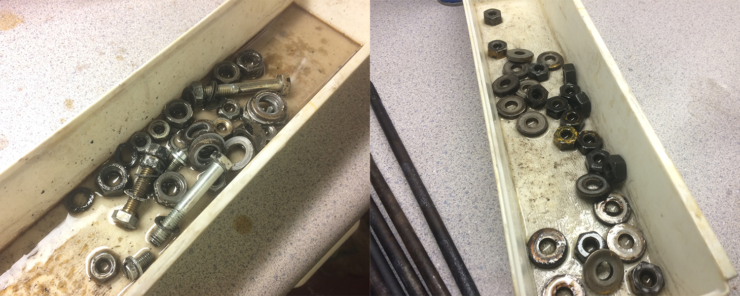
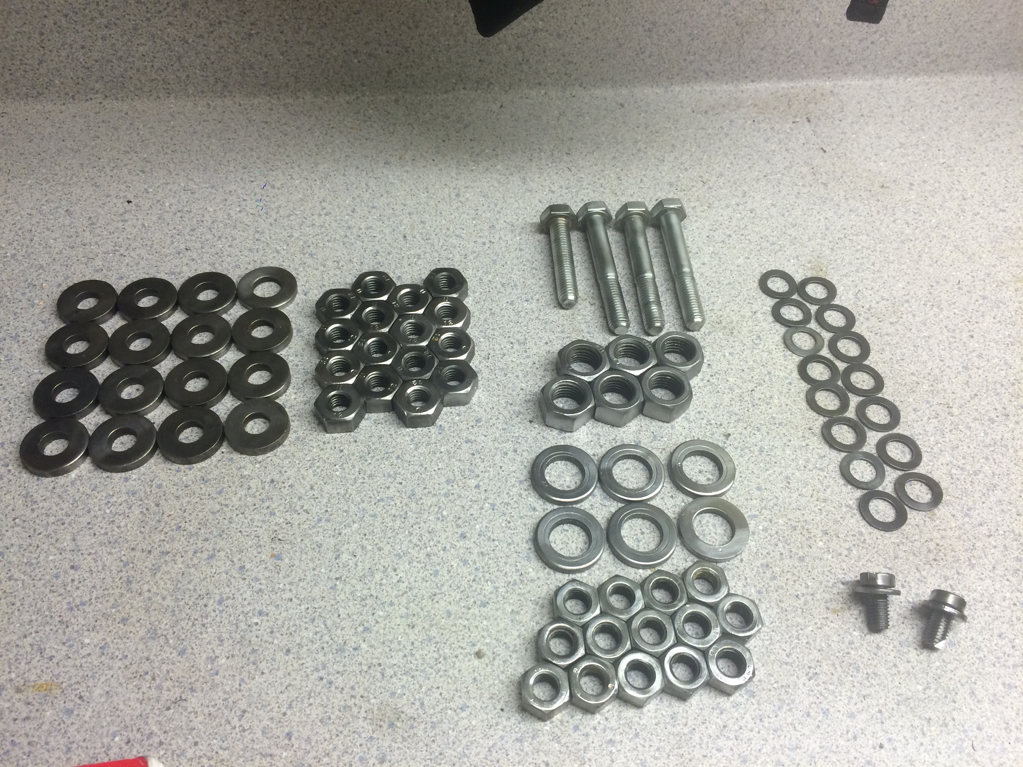
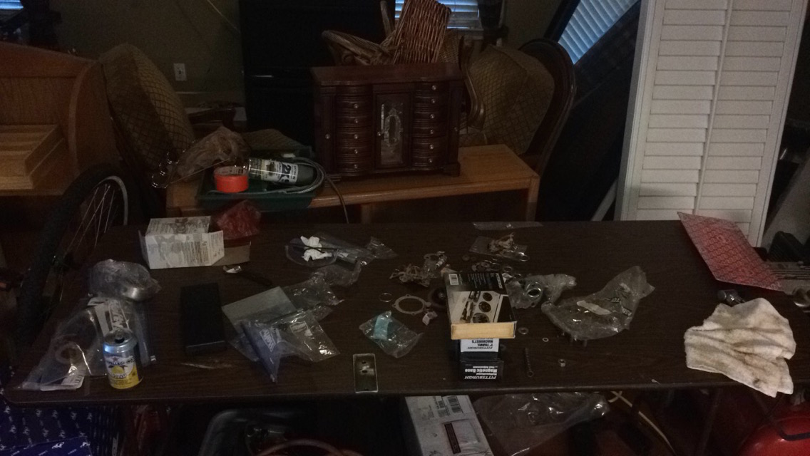
organizing the parts
This was huge time saver. When I disassembled the engine, I made sure I put every bolt, washer, nut, screw, and assembly inside a labeled bag. The first thing I did was organize all of these parts on a table along with the new parts, which made it really simple to do inventory.
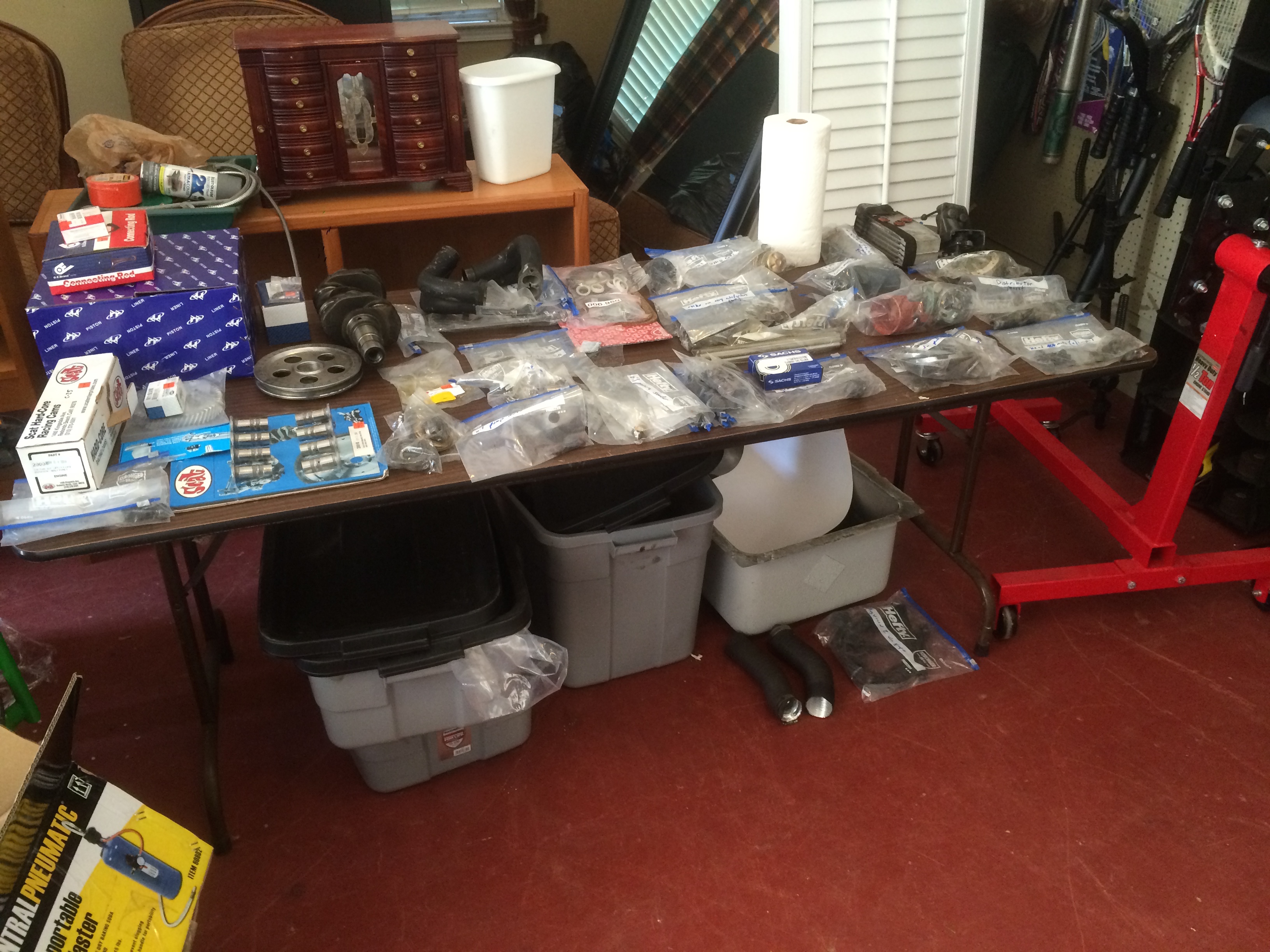
After talking with Clyde at length, I decided to upgrade the heads, pistons + cylinders, and cam. I had Clyde install some heavier duty springs in the heads (which should allow for a slightly higher max RPM due to the faster value return). I also had the engine case bored to accept slightly larger pistons, 90.5mm bore instead of the stock 85.5mm. Combined with the stock 69mm stroke this increases the engine's displacement from 1584cc (quoted by VW as the "1600" engine) to 1776cc. I also went with a Scat racing cam, which will provide slightly higher lift and let the engine breath better. With this I also installed new connecting rods, lifters, oil pump, and all new seals, bearings and gaskets.
prepping the case
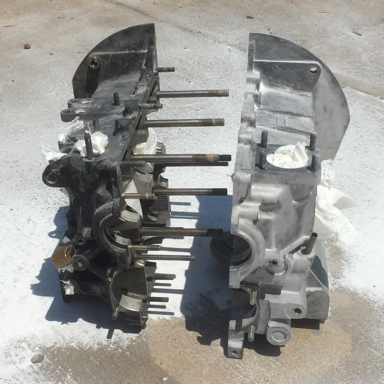
I considered getting the case cleaned ultrasonically, but due to budgetary and time constraints, I decided to soda blast the case myself. I bought a Harbor Freight soda blaster (read -- a shitty soda blaster), and got to work. My family's air compressor (which we've had since I was a toddler) was vastly too wimpy to provide the CFM's that I needed, so a neighbor let me use their huge fifty gallon compressor. I still had a little trouble with oil and/or condensation in the air which kept gumming up the blaster, but I got through it. I was absolutely covered in baking soda after doing this in the hot Georgia summer. I got really sweaty and the powder stuck to me like glue. Here's what one half of the case looks like after blasting compared to the unblasted side.
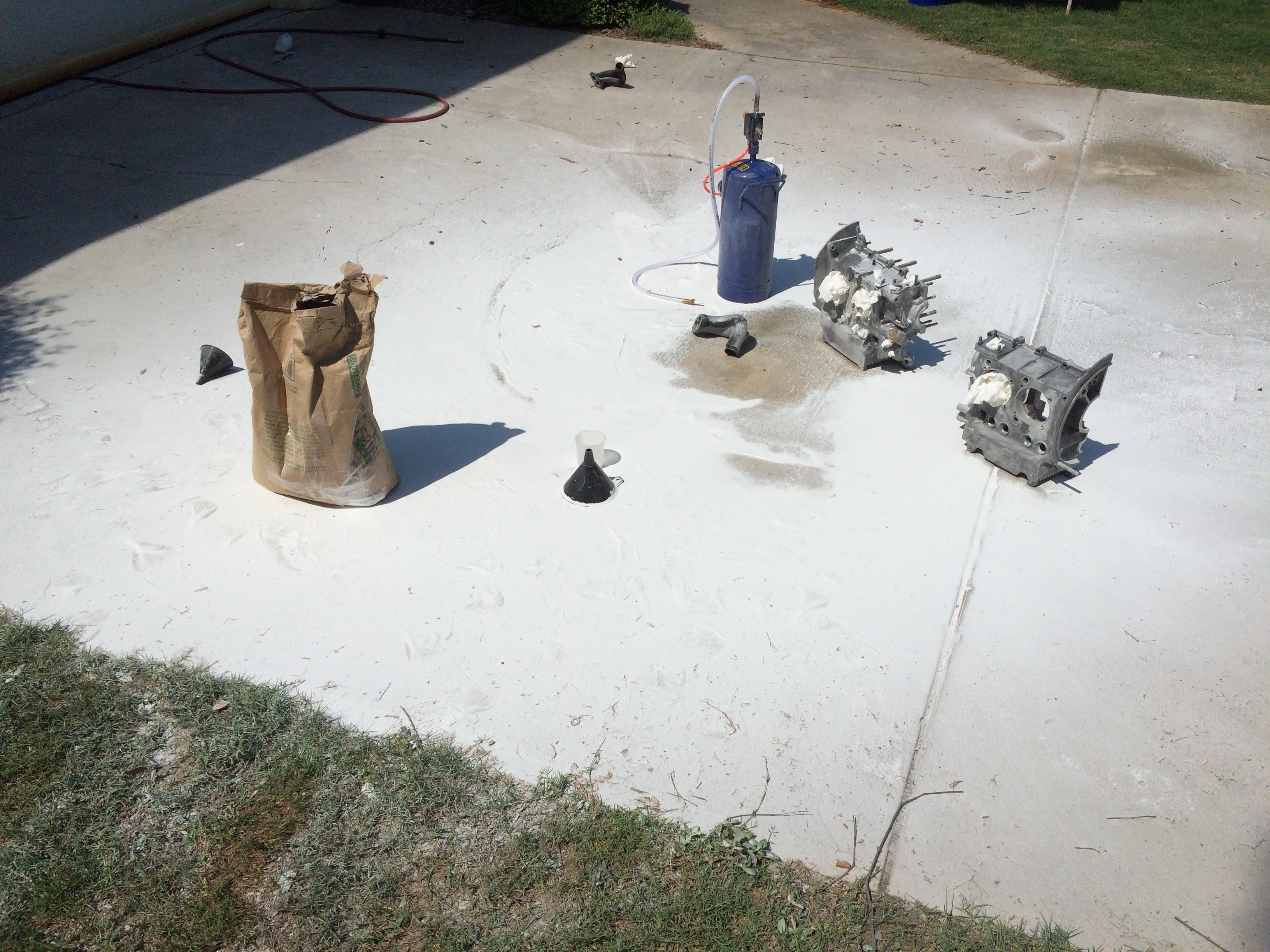
I made sure to plug up the oil galleys, since I wasn't sure if I could ever get the particles out of there, and I made sure to be careful around the bearing surfaces, which I didn't want to mar. You can reclaim the baking soda and pass it through a sieve if you'd like to reclaim it, but I threw it away since the stuff I was using was relatively cheap. Here's the absolute mess I created in the driveway.
I don't have any pictures of the process, but after blasting I washed out the case with a lye solution to make sure that all of the blasting medium was cleared out of the case. I also hand cleaned most of the the inside of the case with a solvent and some shop rags. You really don't want any grains left in the engine, this is honestly more crucial with sandblasting, since the sand won't dissolve in the oil, but I think the baking soda can also cause some damage before it dissolves or is caught in the oil filter. Either way, I didn't want to take any chances.
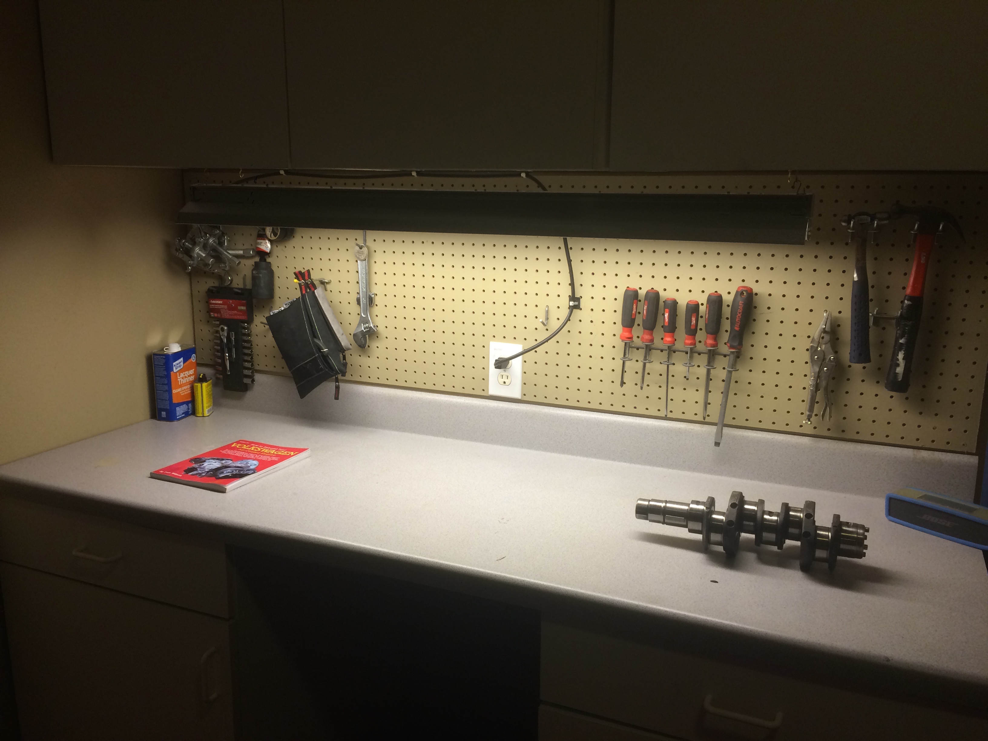
prepping the workshop
Not much to say here. We had a workbench in the garage that was perfect for building the engine on, but it was cluttered and poorly lit. I cleaned the surface off, organized the tools, and installed a little shop light below the cabinetry above. In the photo you can see the great little book that was guiding me through the whole process. How To Rebuild Your Volkswagen Air-Cooled Engine.
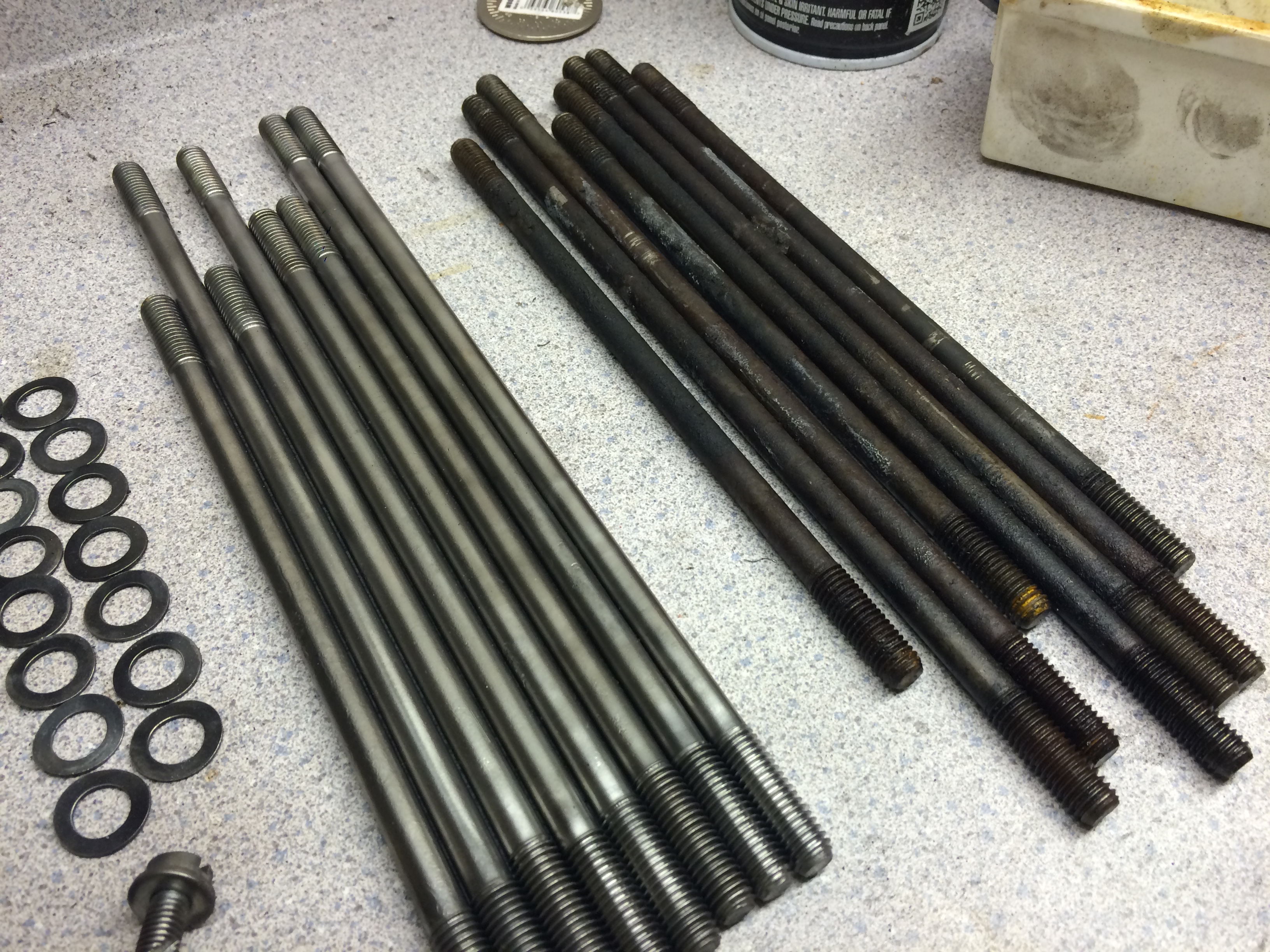
inspecting and cleaning parts
Obviously, I was really skittish about almost everything during this entire process, I probably annoyed Clyde a bit too much during this process, as I was calling about really small things, such as tiny surface scratches on my timing gear. He did a really good job of keeping me calm and directing my eyes to the prize. I inspected any crucial metal parts I was reusing, and I spent the better part of an afternoon scrubbing nuts and bolts with solvent and cleaning them up on the wire brush. I launched a good number of nuts across the garage.
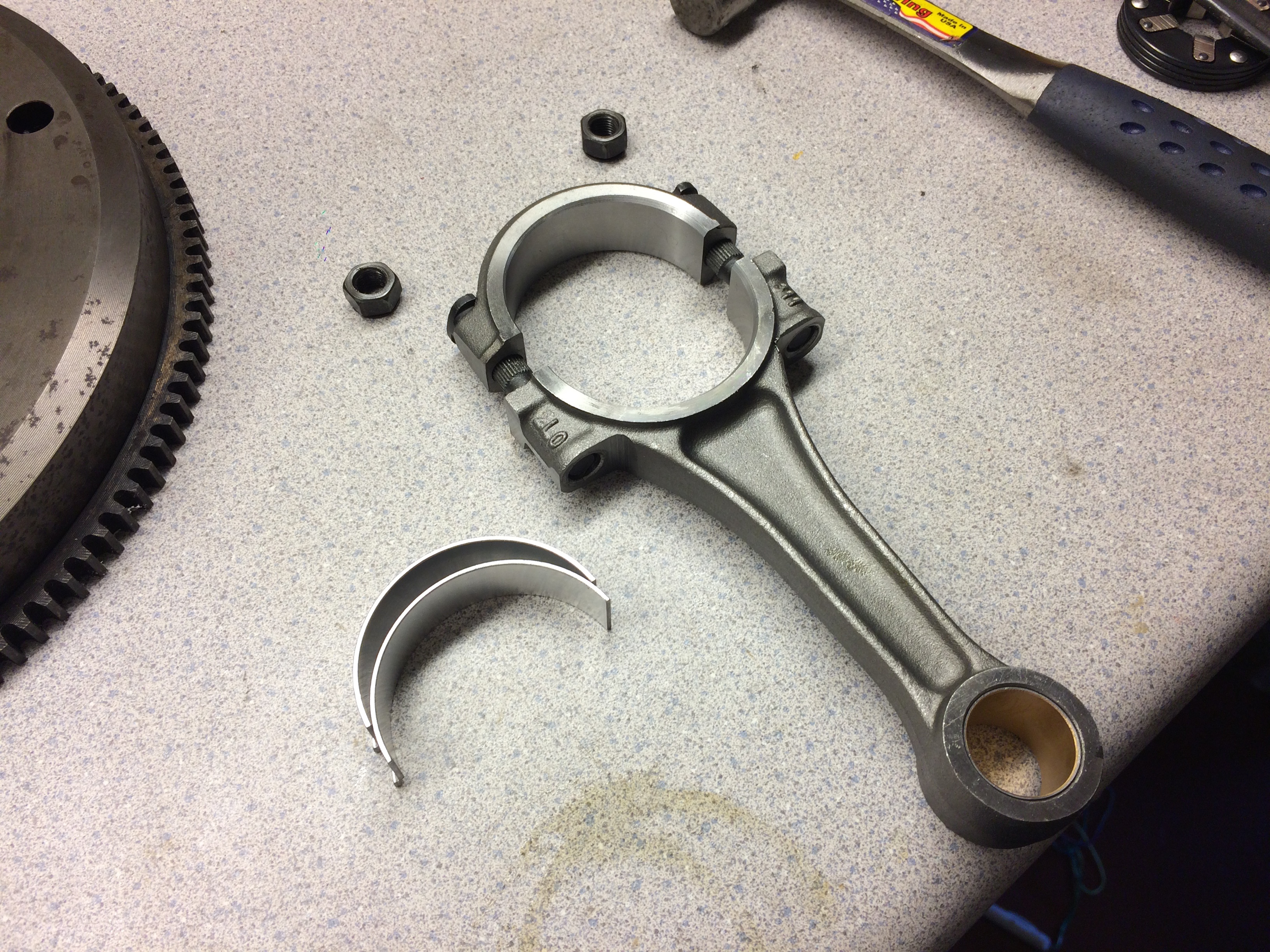
short block assembly
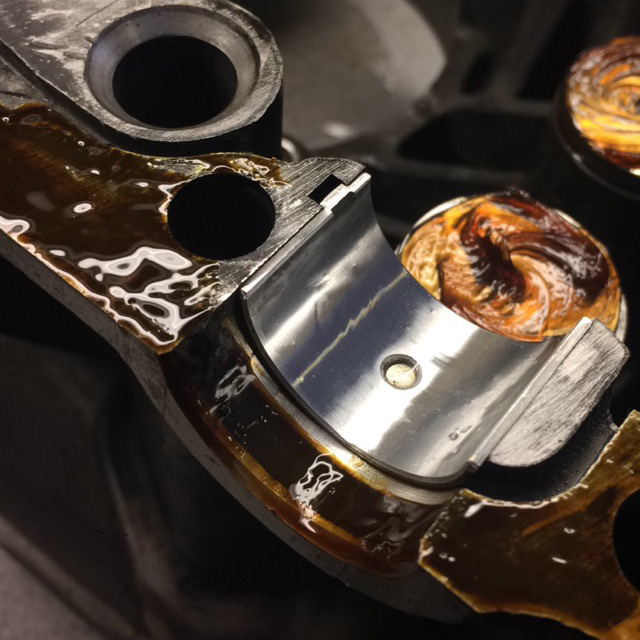
From here I essentially followed the instructions outlined in the book. First came the connecting rods. I used plastiguage to check the bearing clearance to the crank. You put a little strip of plastic between the bearing and the crankshaft, torque the rods to spec, remove them, and then it's final width tells you the clearance between the two surfaces.
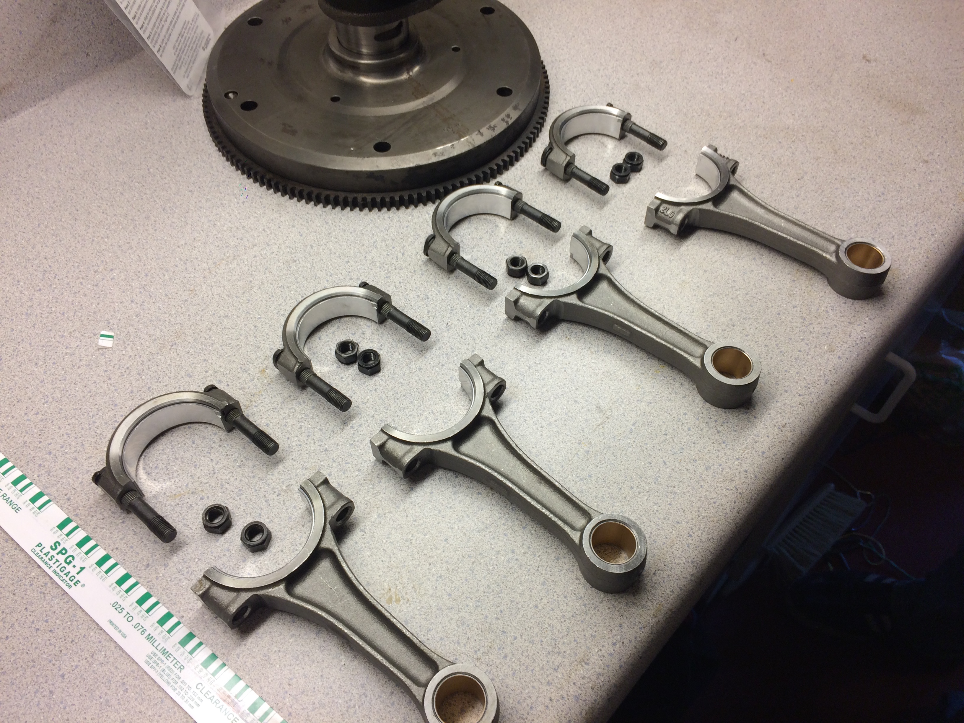
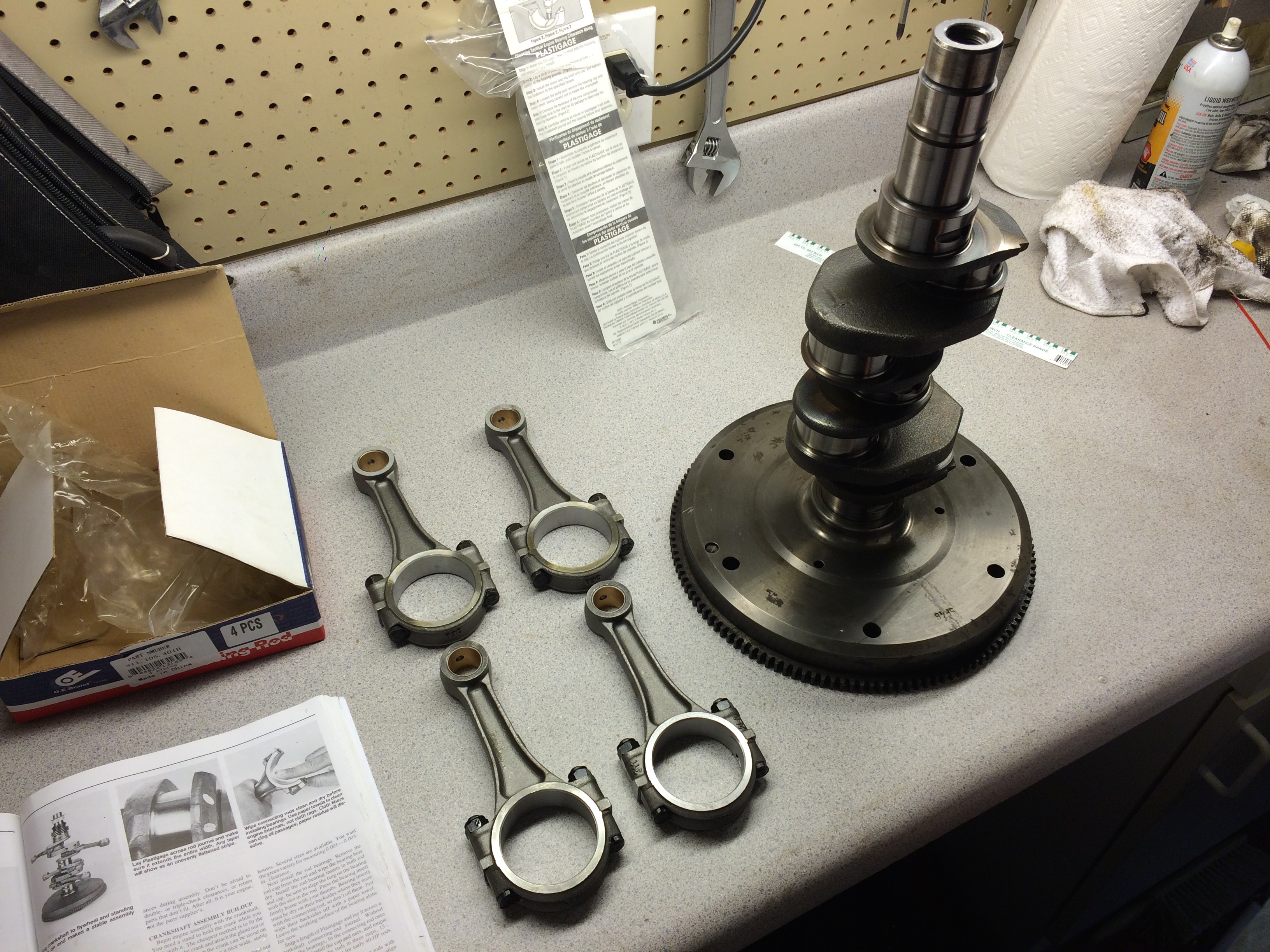
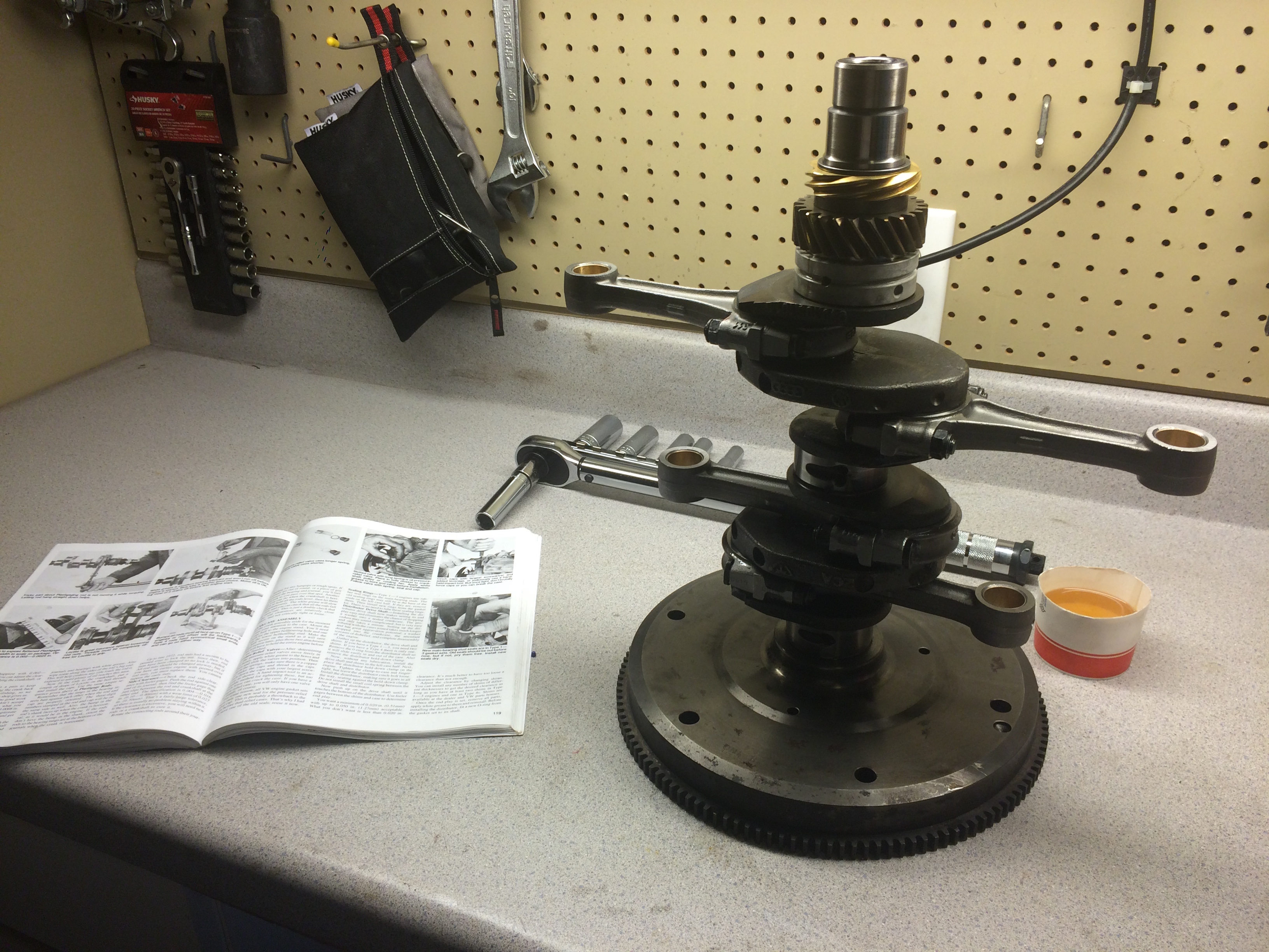
Before final attachment of the rods, I put the crankshaft and timing gears on, in arguably the most stressful operation. The gears have to be heated in an oven to stretch them out, and then placed on in the correct order and orientation. I probably re-read the passages in the book that described this operation ten to fifteen times before I felt confident enough to attempt it. This operation requires specific pulling tools to reverse, so I didn't want to mess up this step. After these parts are on, then the rods can be attached and torqued to spec, which completes the assembly of the crank. There are still some spacers, a bearing and a oil slinger that must be placed onto the crank, but I waited until the crank was placed into the case to put these parts on. Do not forget to insert the pulley key. I did, and it caused me lots of headache further down the road since it is almost completely inaccessible after the case halves are mated.
I think here is where I really realized how much work I still had ahead of me, which caused my pictures to become less frequent and more sloppy, so, apologies for that.
I prepared the right side of the case (passenger side) on the workbench. This involved placing the lifters into their seats, prepping the lifter surfaces with the lapping compound (a slightly abrasive compound that helps the camshaft mate with the lifters during first operation, note, you do not want this compound on any other surfaces inside the case), inserting the bearing pins and bearings into their seats, inserting the cam bearings, coating the rim of the case with an aviation grade gasket making compound (Permatex Aviation Form-A-Gasket No. 3) and inserting the cam plug.
There is much debate about the gasket compound, RTV is strictly frowned upon, most people go with this Permatex stuff. I actually visited a specific store near Atlanta to pick up this tiny bottle of nasty stuff. Any silicon based sealant is avoided because the case halves need to be sealed, but not spaced very far apart. It's also very difficult to get off if you mess up, which creates even more of a headache. Before applying the sealant, I scraped the surface lightly to remove any last remnants of the previous gasket maker, and finished off the cleaning with acetone to remove any of my hand oils. I made sure not to get gasket maker on any of the bearing surfaces.
I had lots of small challenges during this part. I was very nervous about the quality of the bearing seats in the case. I sent lots of photos to Clyde to make sure everything looked okay. There was some black and brown streaks in some of the bearing seats but I couldn't feel any ridges or scarring. I also had trouble identifying which cam bearings went in what slots, it was very ambiguous and took a while to figure out. Applying the case sealant was also really stressful, it's very tree-sap like, it gets everywhere and it doesn't come off easily.
Similar steps were carried out on the left side of the case, inserting the lifters and bearing pins, inserting the spring-loaded oil galley valves (they keep cold, high-pressure oil from flowing to the oil cooler until the oil warms up a bit to drop the pressure), and checking the lateral clearance between the cam bearing flanges and the camshaft. With some help with my mom, I placed the crank into the bottom half, making sure the pins lined up into the bearings that were slid onto the crank. I also inserted the distributor shaft at this point. This can be done after the case halves are mated, but it requires a pulling tool to remove if not inserted correctly. It's semi-critical to ensure the gear is mating at the correct place, as you want the shaft to be somewhat in the right location. Timing adjustment will rotate the body of the distributor slightly, but the gross placement is set using the mating of these gears. The little gaskets that go on the case half studs.
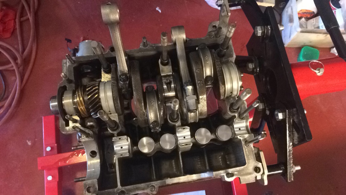
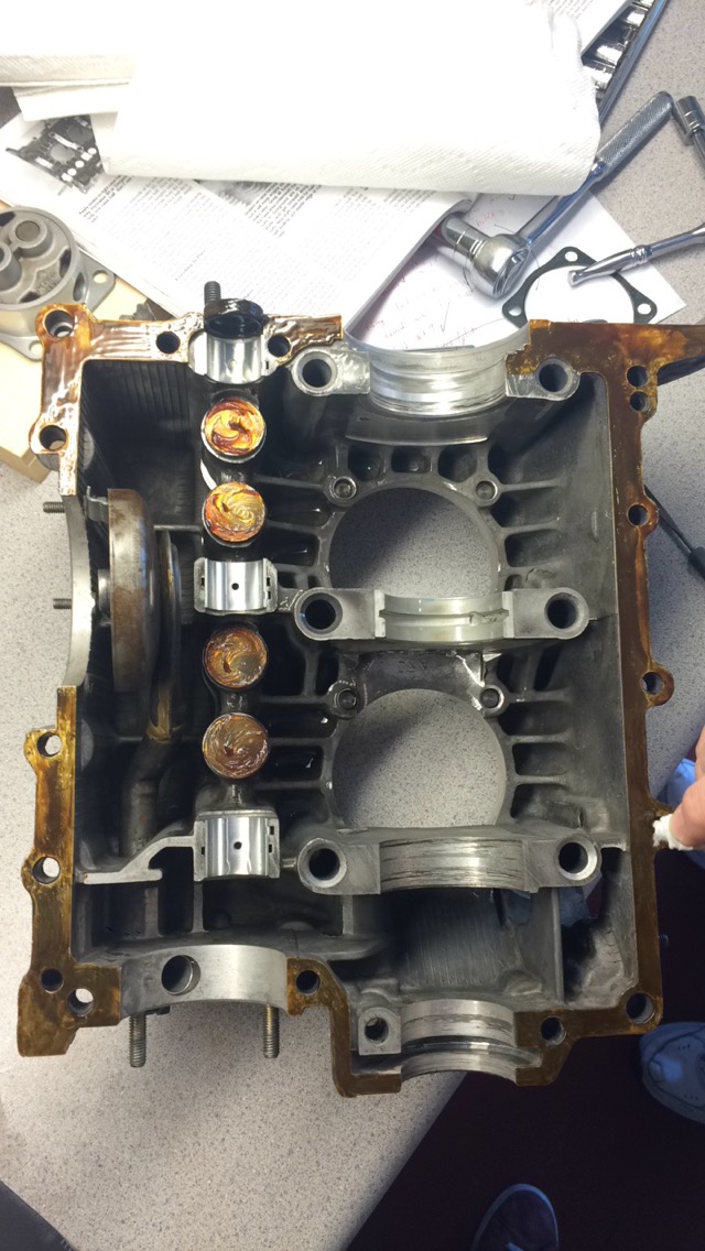
I applied the lapping compound to the lifters and installed the camshaft. You have to make sure that the cam gear on the camshaft is mating in the right position with the cam gear on the crankshaft. There are dots to assist with this. If this part is not correct, even if the alignment is off by one tooth, the engine will most likely not run. This placement ensures that the cam is in sync with the crank, since the valves need to open at the correct point in each stroke. After one last check, I mated the case halves and installed the studs.

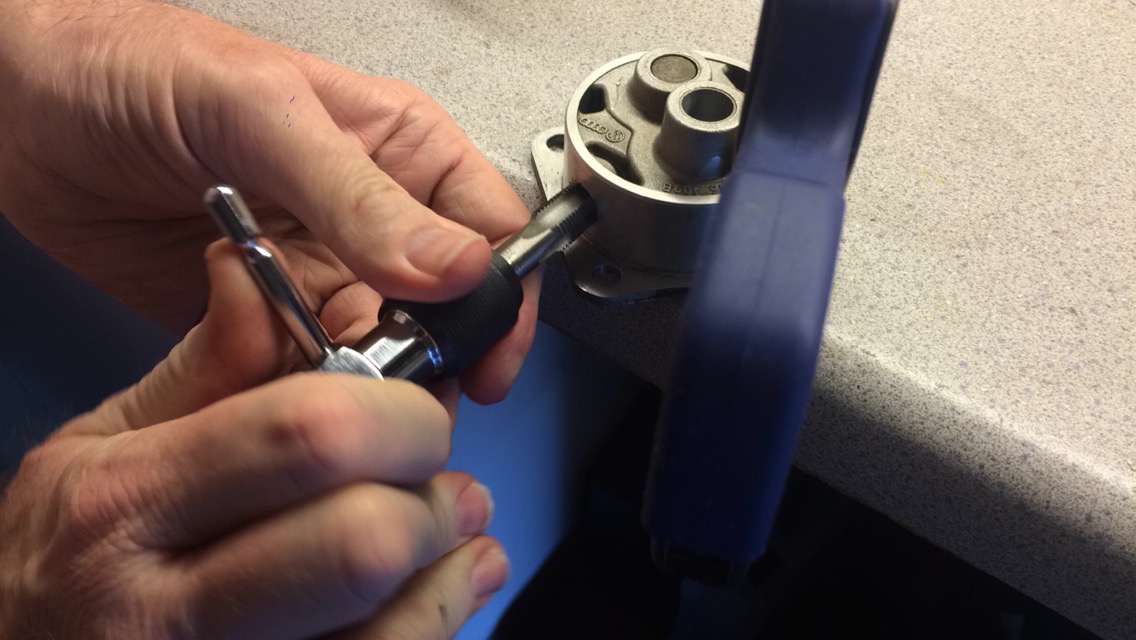
In this photo, you can also see the little bronze fitting that Clyde installed in my case. This is a popular modification that allows for an external oil filter to be installed. A plug is installed in the outlet of the oil pump body, and a custom oil pump cover is placed on the oil pump which has another fitting. The oil is forced out the cover, fed through an external filter, and then flows back into the engine through the bronze fitting that was installed on one of the oil galleys. This should vastly improve the life of the engine, as stock, the engine only has a coarse strainer which captures large objects. Of course, this is almost useless, as large objects in the strainer almost certainly signify engine death. I bought this kit from Gene Burg Enterprises, it came with the oil filter mount, a filter, and braided tubing to wire everything up. Here's the oil pump body being tapped to accept the NPT plug.
I did make one mistake when installing the oil pump. It takes quite a bit of force to squeeze the pump body into the space left for it when the two case halves were mated. The assembly guide recommends a block of wood and a hammer to ease installation, so that's what I did. I reached a point of high resistance and figured it was normal, until one corner of the flange on the pump body broke off. I backed the pump back out and found a bolt head shaped divot in the back of the pump, which means I was hammering the pump up against the camshaft gear. I called Clyde and quickly figured out that I needed to install a lower profile pump because I had used a different profile cam gear. I purchased the new pump from Clyde, re-tapped the new outlet port, and installed the pump.
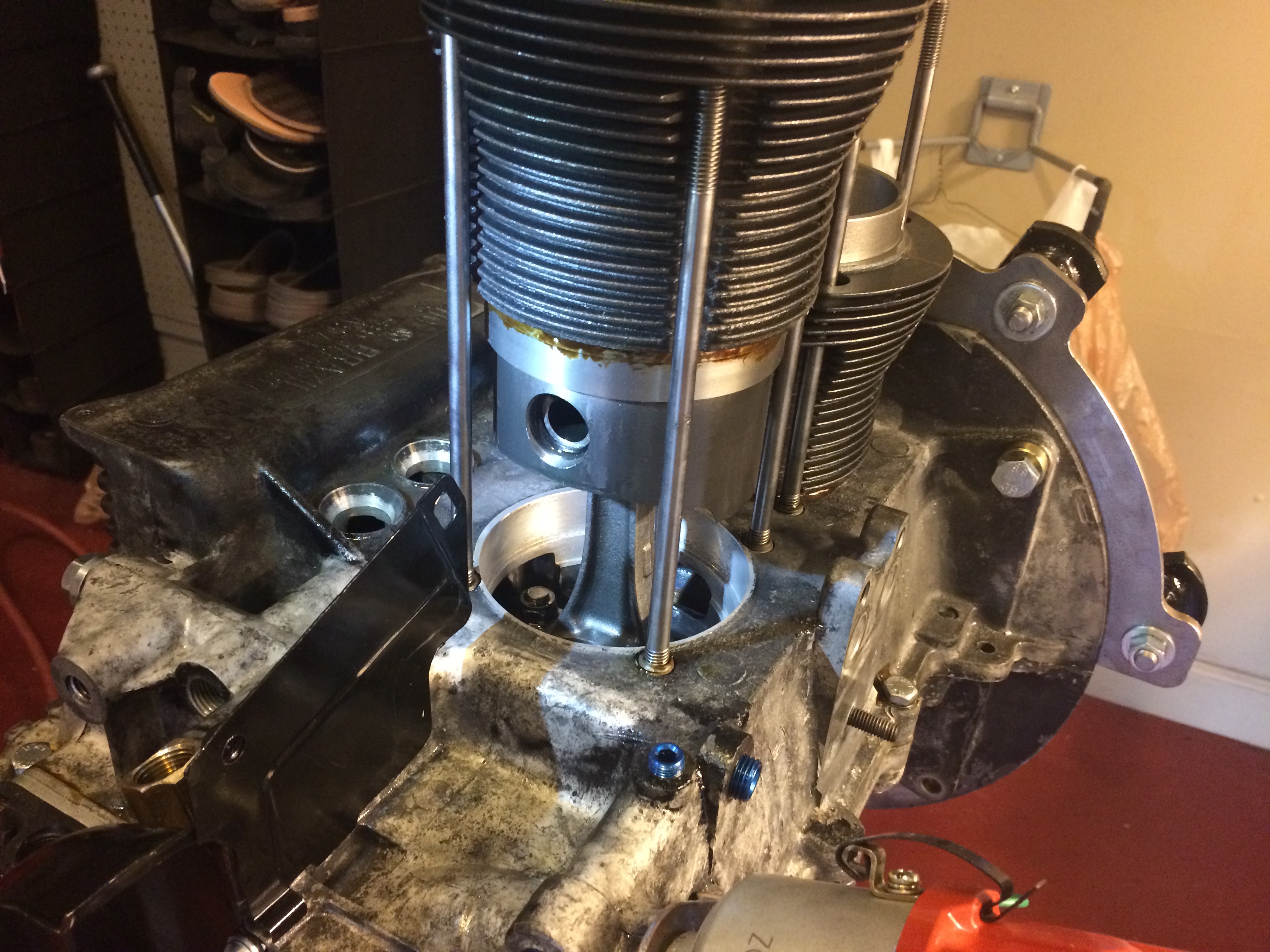
Next the pistons were partially inserted into their cylinders before the cylinders were slid partially onto the studs to allow for the wrist pins to be inserted. Very important and difficult to get right was the rotation of the three rings. I read a bit on the subject and went with Clyde's recommendations. You want to align them such that no opening is at the bottom (closest to the ground), since this would allow oil to seep through between the rings when the engine is stopped, creating smoke during each engine start. I also made sure the rings weren't all aligned with one another, as this would increase the chance for blow-by.

Before final piston installation, the deck height of each cylinder was measured using feeler gages and a piece of metal across the top of the cylinder. The data on each cylinder was recorded and was used to determine which metal spacer should be placed below the cylinder. This, combined with the measurement of the CC's of head allowed for the calculation of total displacement of each cylinder. Different metal spacers adjust the deck hight up and down and allows for the compression ratio to be set. This is critical. For final installation of the cylinders, I put gasket maker around the bottom seat of each cylinder, this is recommended but not necessary.
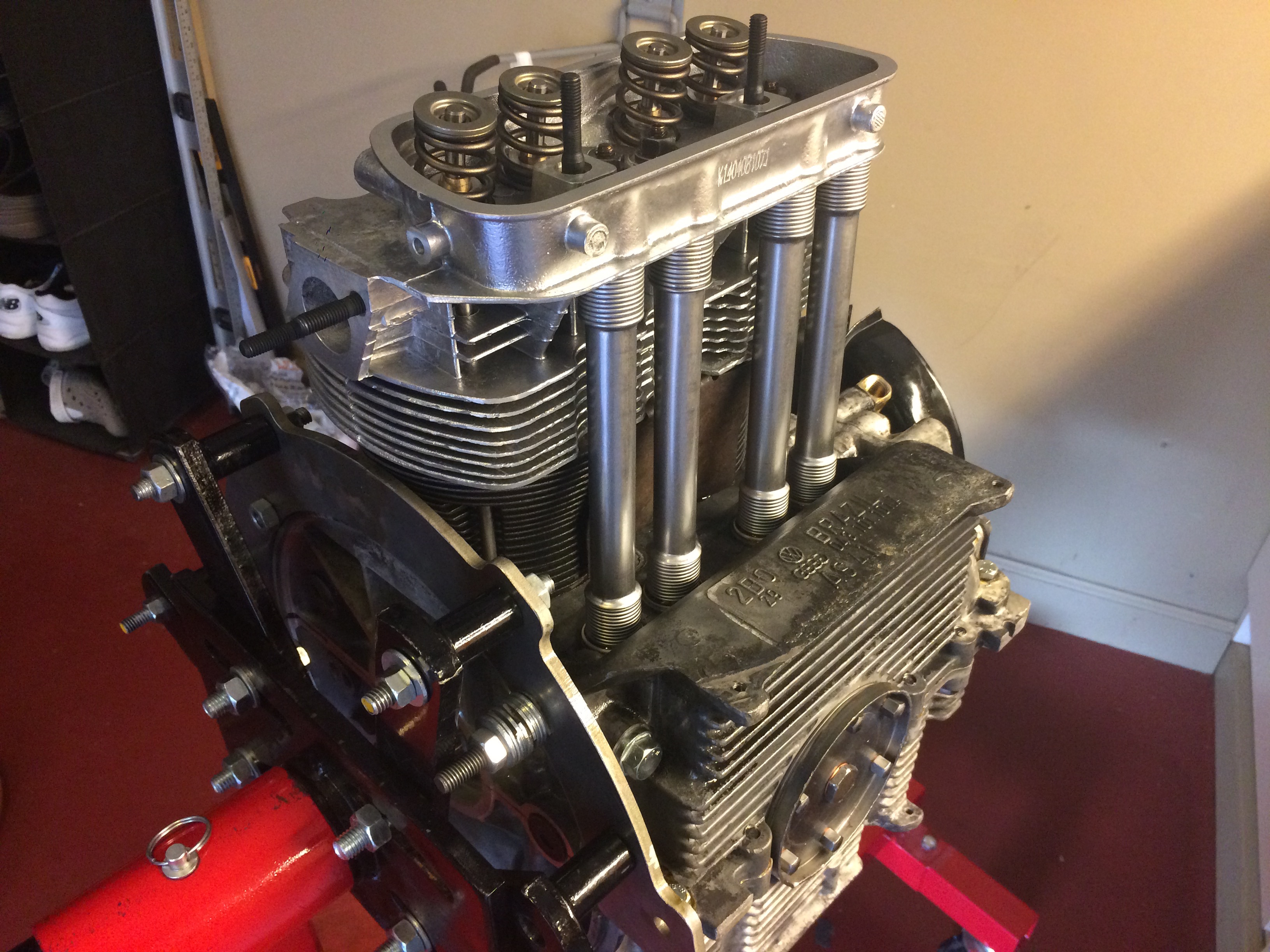
The pushrod tubes and their seals were sightly expanded (they work almost like a bendy straw) and then placed into their seats in the case with some gasket maker. Gasket maker was also placed on the pushrod seals that mate with the head. The head could then be installed and torqued, making sure that the pushrod tubes are seating well into the head. This process (final installation of pistons and cylinders (not the measurements), pushrod tube placement and head installation) was then repeated for the other side of the case. (The photo with both heads installed is from a little later in the build, but it fits here as well)
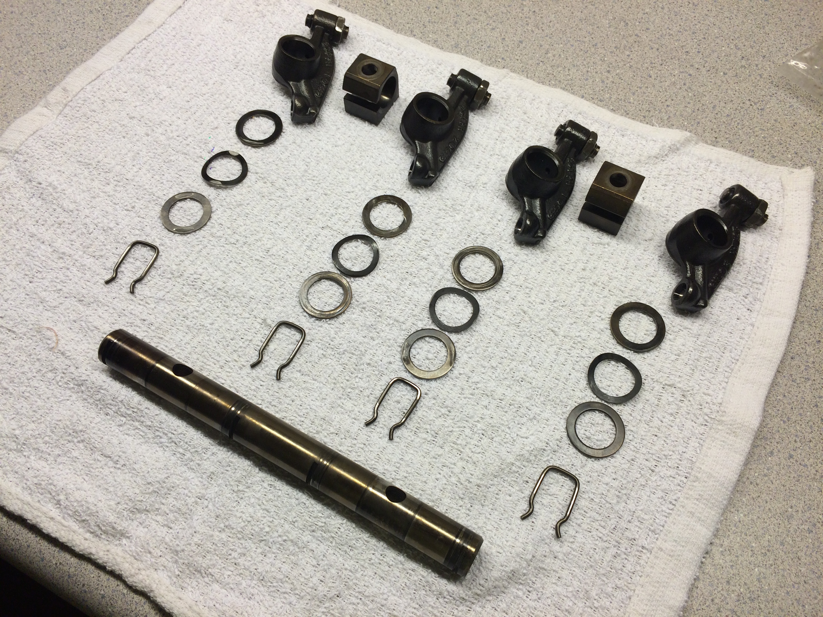
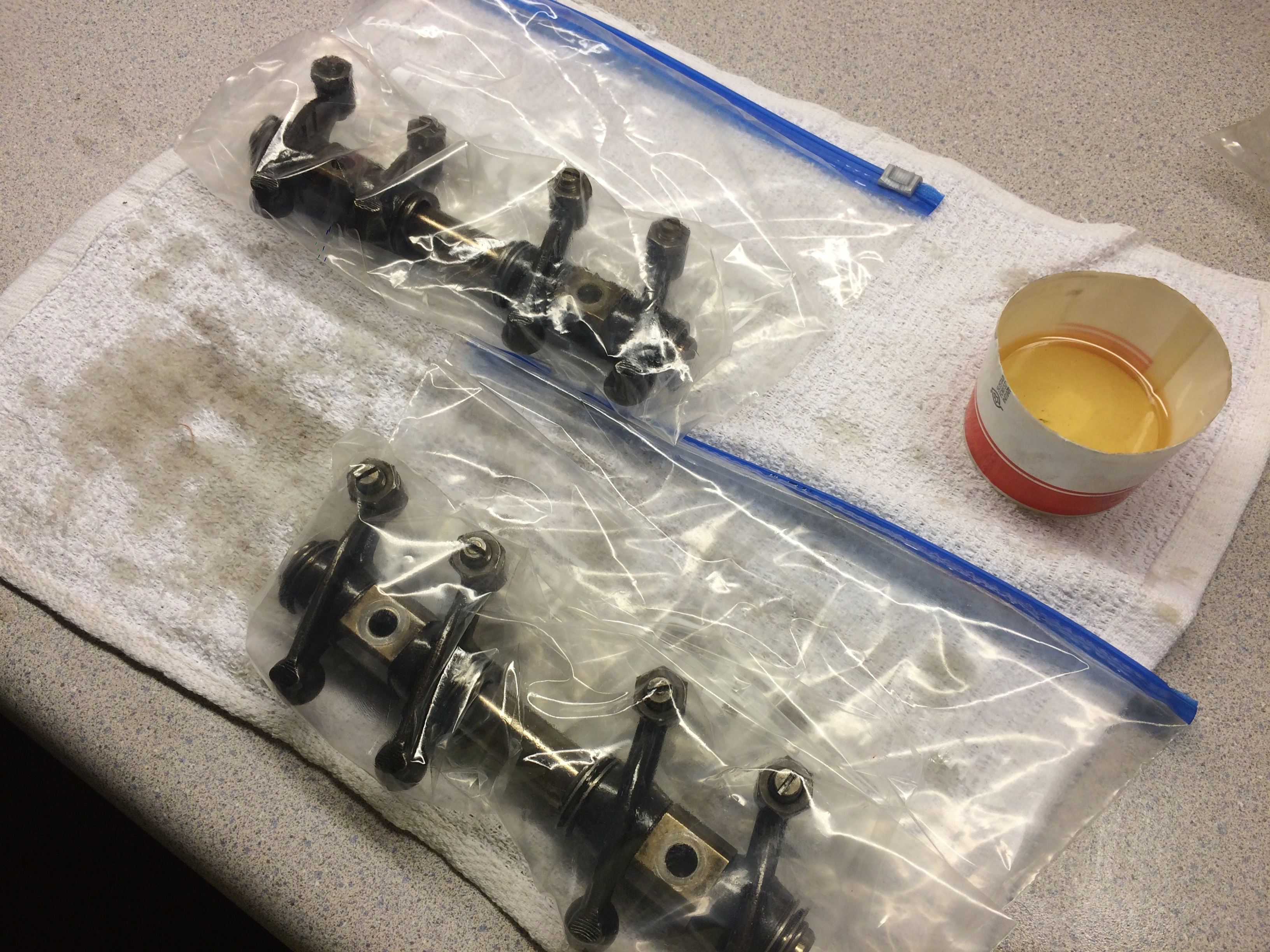
I had previously disassembled, cleaned, assembled and re-oiled each rocker arm assembly and stored them oiled in bags. These were installed, along with the pushrods, into each head and torqued to spec, making sure that the "wavy washers" were oriented correctly. This should help prevent the nuts from backing back out due to vibration.
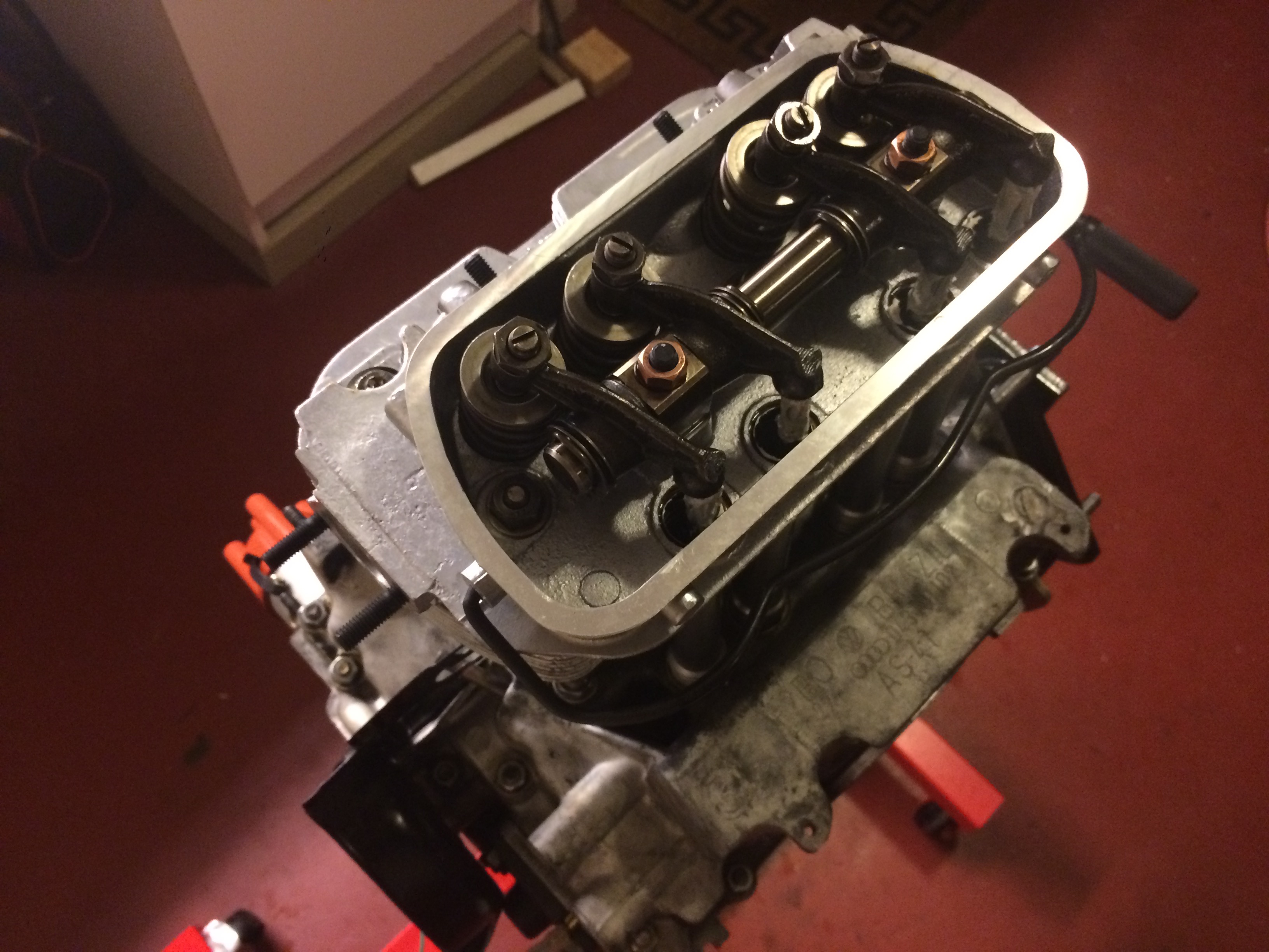
top end assembly
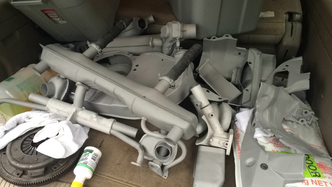
I briefly considered ordering new engine tin, but considering the cost and the time frame, I decided to paint mine. I was going to use the soda blaster to strip the old paint and any rust, but after remembering my previous experiences with it, I decided to take it to a local sandblasting shop. They took the paint, oil and rust off of all of the tin in an hour for about fifty dollars. Well worth it. I also them blast the exhaust, intake manifolds, heater boxes, and alternator stand.
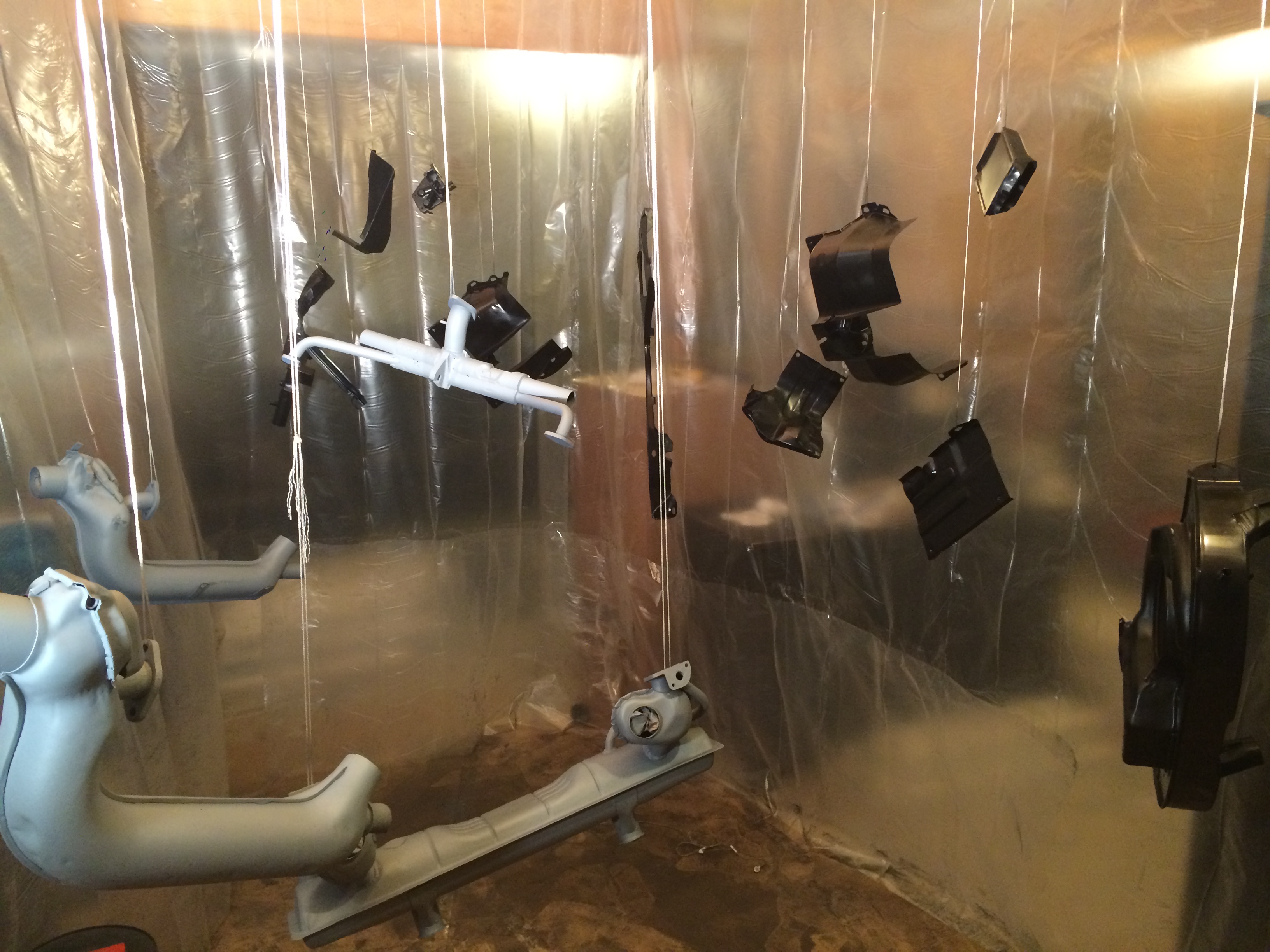
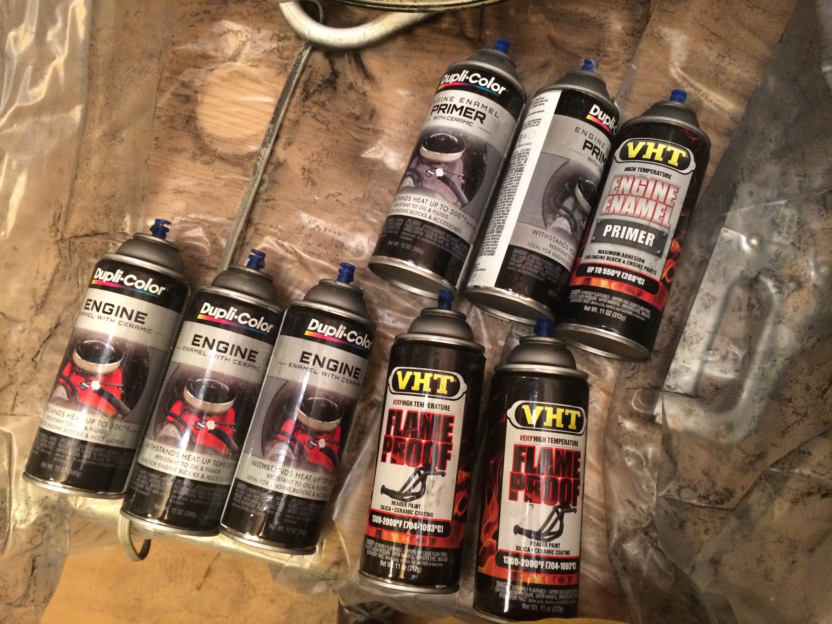
After I got the parts back, I setup a very janky paint booth in my basement with some plastic sheeting for the walls and butchers paper for the floor (to my parents' dismay) and hung the parts from the ceiling. I made sure to use masking tape and wads of newspaper to block off any holes I didn't want to get paint or primer into. A fan was also placed in the window that was in the "booth" and was used as an exhaust fan to keep the fumes out. I used a high temp primer and paint from the auto parts store for all of the parts, and for the muffler and heater boxes I used an extra high temp "flame proof" primer and paint. Not sure if this was totally necessary, but I didn't want to risk it. This process was a little cramped, I felt like a contortionist attempting to squeeze around all of the wet parts and not nick the paint with my clothing. I succeeded for the most part, but I wish I had more time so I could have done the parts in a rotation. I ended up with paint on almost every part of by body, which didn't come off for a day or two.
Next was the assembly of the top-end. The first thing to install was the pulley wheel. I realized a critical error here, I had forgotten to install the key in the crankshaft that mates with the pulley wheel. Now that the case halves were mated the keyseat was located inside a flange in the case, which makes it difficult to put force downwards in the key to seat it. I thought about using a punch and using the flange as a lever to exert force downwards onto the key, but I was worried about marring the surface of the case. I was able to insert the key by hand and some careful tapping with a hammer and a piece of rod, but couldn't get it to sit level in it's seat. A family friend / mechanic gave me a great solution, just put the pulley wheel on and let the keyway do the work. This worked perfectly, I was able to use the bolt that holds the pulley on to slowly push the pulley onto the key and let the problem work itself out.
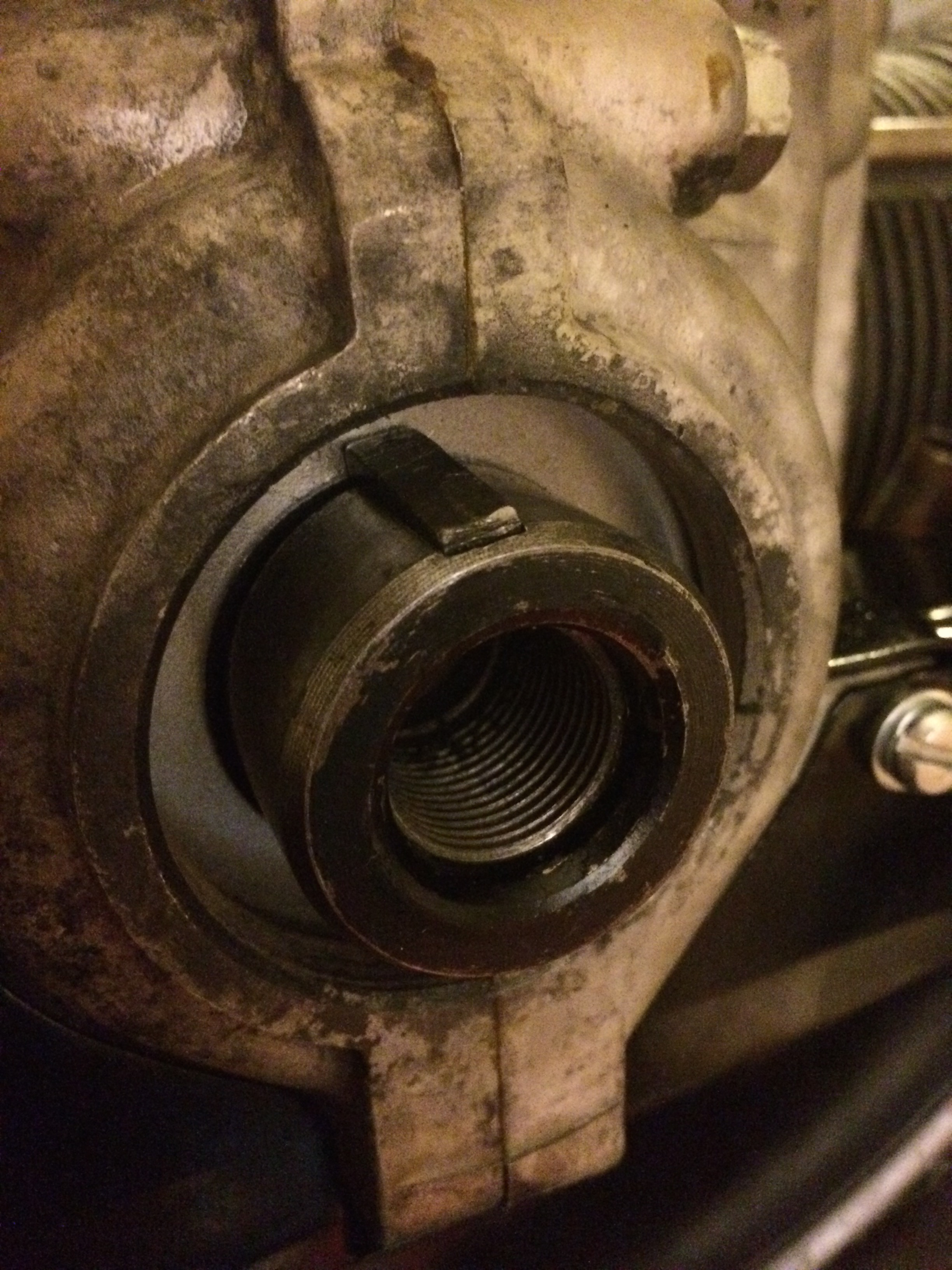
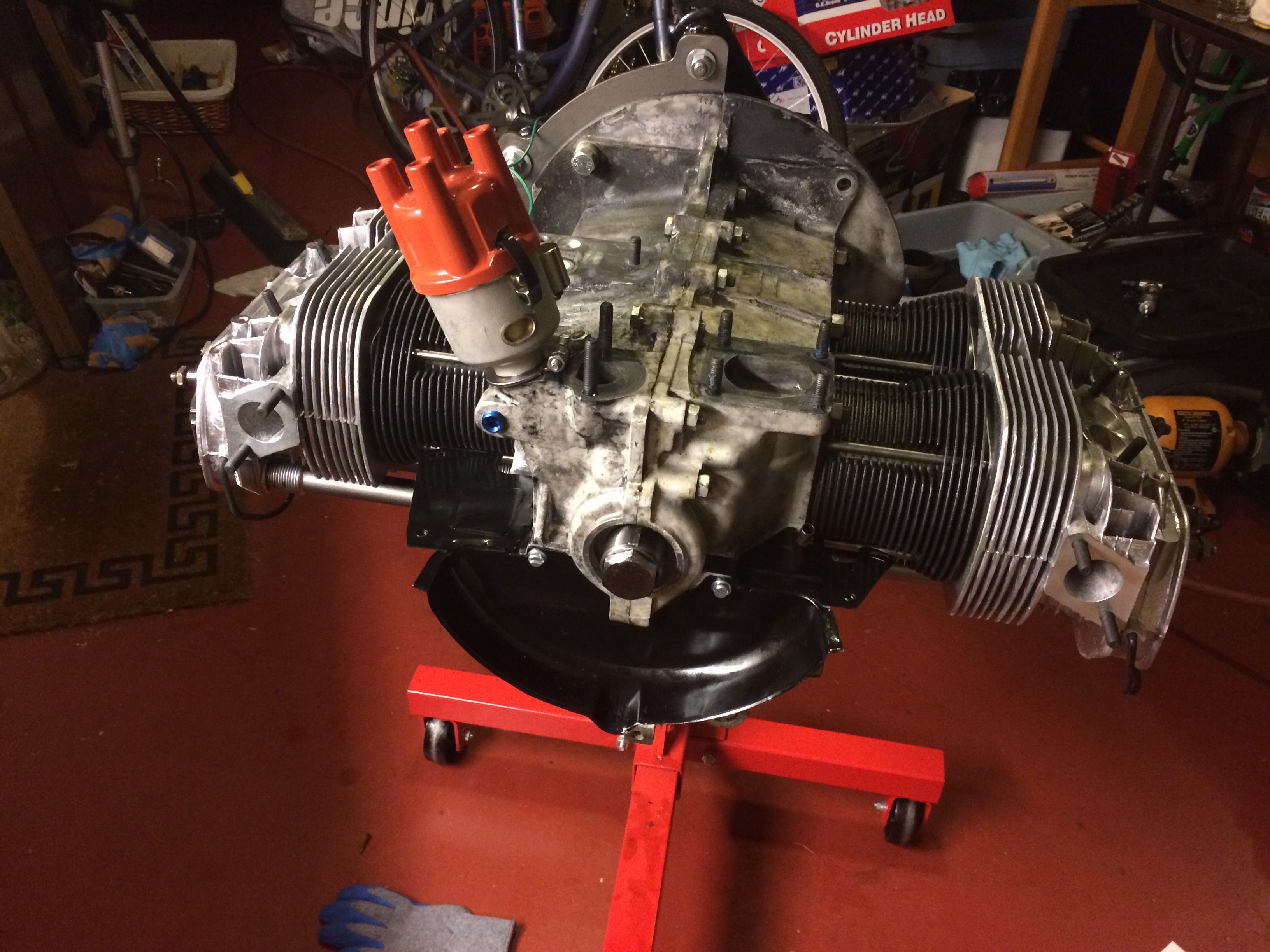
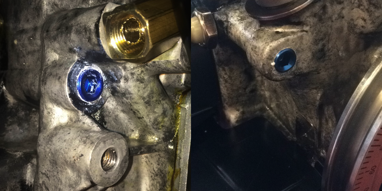
I installed NPT caps into the holes that were drilled and tapped in the case by Clyde when he modified my case for the full flow oil system. He drilled these holes in order to evacuate the oil galleys of any stray metal shavings that may have been left behind by the tapping of the main oil return galley. These shavings would cause havoc if present, especially during initial start up. These tapered NPT threads are really stressful, it's difficult to know when you're tight enough to keep the seal liquid-tight. If the cap is too loose it will create an oil leak, and if you attempt to over-tighten them you can strip the thread, or crack the engine case. You can also see the oil pressure switch and pulley installed in this photo.
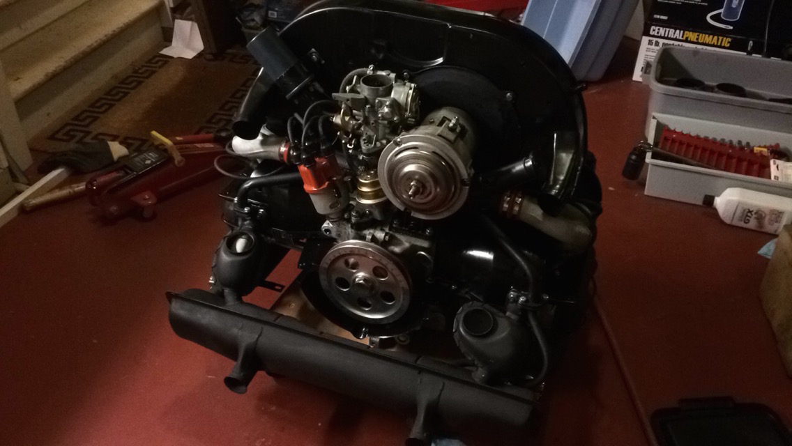
Now things started to just bolt on to the short block. Next was the fuel pump (stem, shaft and pump body), intake manifolds (the heat riser, rubber boots, and manifolds that bolt to the heads), alternator stand / oil filler tube, oil cooler, heater boxes, muffler, valve covers, and most of the tin above the heads and cylinders. My parts were all a little bent, so they took a little convincing with the assembly hardware to pull them together. The most difficult part was getting the heat risers (part of the intake) lined up with the muffler, because the muffler also has to connect to the heater boxes (connected to the rear cylinders), line up with the exhaust ports on the front cylinders. Further complicating this process are the little pieces that are slid over the exhaust header on cylinders two and four, which have to be situated to connect with the fresh air ports on the front of the heater boxes. This process involved a lot of loosening and re-tightening parts to do fine adjustments.
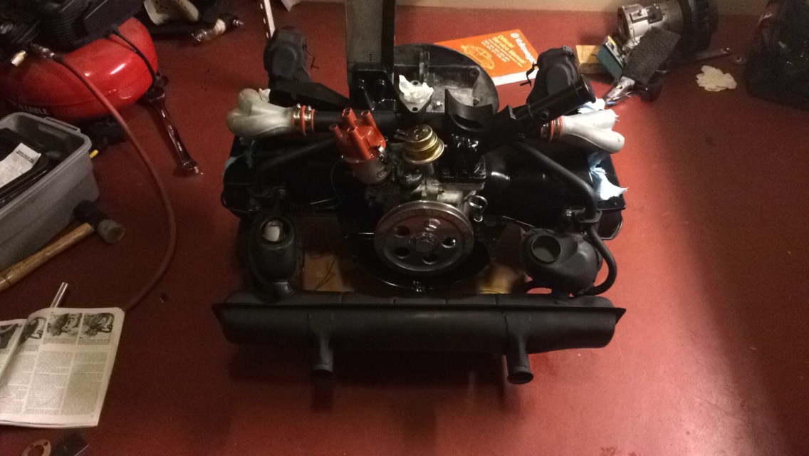
Next was the carburetor, which I didn't rebuild, but annihilated with carb and choke cleaner before attaching it to the engine. I attached the fan and cover plate to the alternator shaft and inserted it into the fan shroud and attached the fan shroud to the engine. I installed the coil on the fan shroud, and connected all of the plug wires, leaving the spark plugs loose in their respective holes (before the first startup, the engine is cranked without the spark plugs attached to build up oil pressure). Not shown in the pictures is the flywheel which I touched up the surface of using a high-grit abrasive sanding pad on a right-angle pneumatic sanding tool. The right angle allowed me to make sure that I was sanding mostly parallel to the surface of the flywheel. A new flywheel seal was inserted, and the clutch plate and pressure plate were attached to the flywheel using a plastic alignment stick (basically a really short transmission shaft with splines on the end) which ensures that the clutch plate is centered in the flywheel and pressure plate. I also installed a new throwout bearing, because they're relatively cheap, there's really no reason not to at this point, mine was rusting from being in my driveway for almost nine months, so it needed to be replaced.
engine installation and break-in
My dad and I jacked the car as high as our paltry hydraulic jack would allow, and then inserted these ramps under the rear wheels as a precaution. Our jackstands were unable to reach the frame with the car at this height, we could have put the jackstands on some wood blocks, but we weren't going to be getting under the car with it at this height, and we felt the ramps provided enough protection. The engine was rolled out of the garage on a cart and, with a slight tilt to allow the fan shroud to clear the rear body panel, moved under the car.

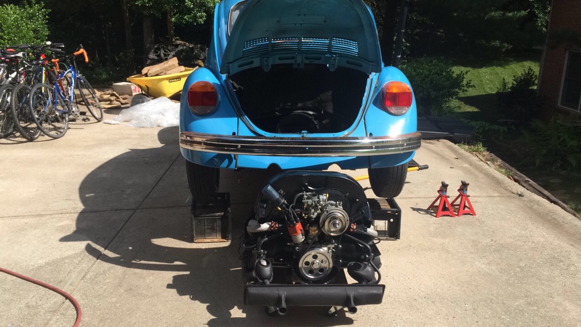
At this point, we took the alternator pulley off, it became clear that the engine wasn't going to clear the hole in the body without doing so. Then the car was slowly lowered onto the engine, making sure that it lined up with the transmission bell housing. We had to tilt the engine towards the back of the car to let the transmission shaft clear the pressure plate and then tilt it forward to slide the shaft into the engine. It took a pretty good push to get the shaft to seat fully. The jack stands were placed under the car at this point, which allowed me to get under the car and install the four mounting bolts. By far the most painful are the top two, which are very difficult to locate. Your head doesn't fit too well up in the space where they are located, so they have to be inserted mostly by feel.
I stopped taking pictures at this point. The engine was inserted into the car the day before I needed to leave up to Baltimore, and I ultimately did not finish the installation before having to make the trip with my dad's car. Before leaving I did manage to get almost 99% of the final assembly done, there just wasn't enough time to break the engine in and make sure it was in working order before making the drive, and even then, I wasn't too keen on having the first long drive being one that absolutely needed to be completed. Before I left, I connected the fuel lines, installed the last bits of engine tin inside the engine bay, installed the throttle cable and throttle cable guide tube, installed the oil strainer air intake and oil pressure relief tube, and mounted the external oil filter mount to the frame. As I was leaving, it was pretty incredible to look at the table that started covered in parts to see how far I had come.
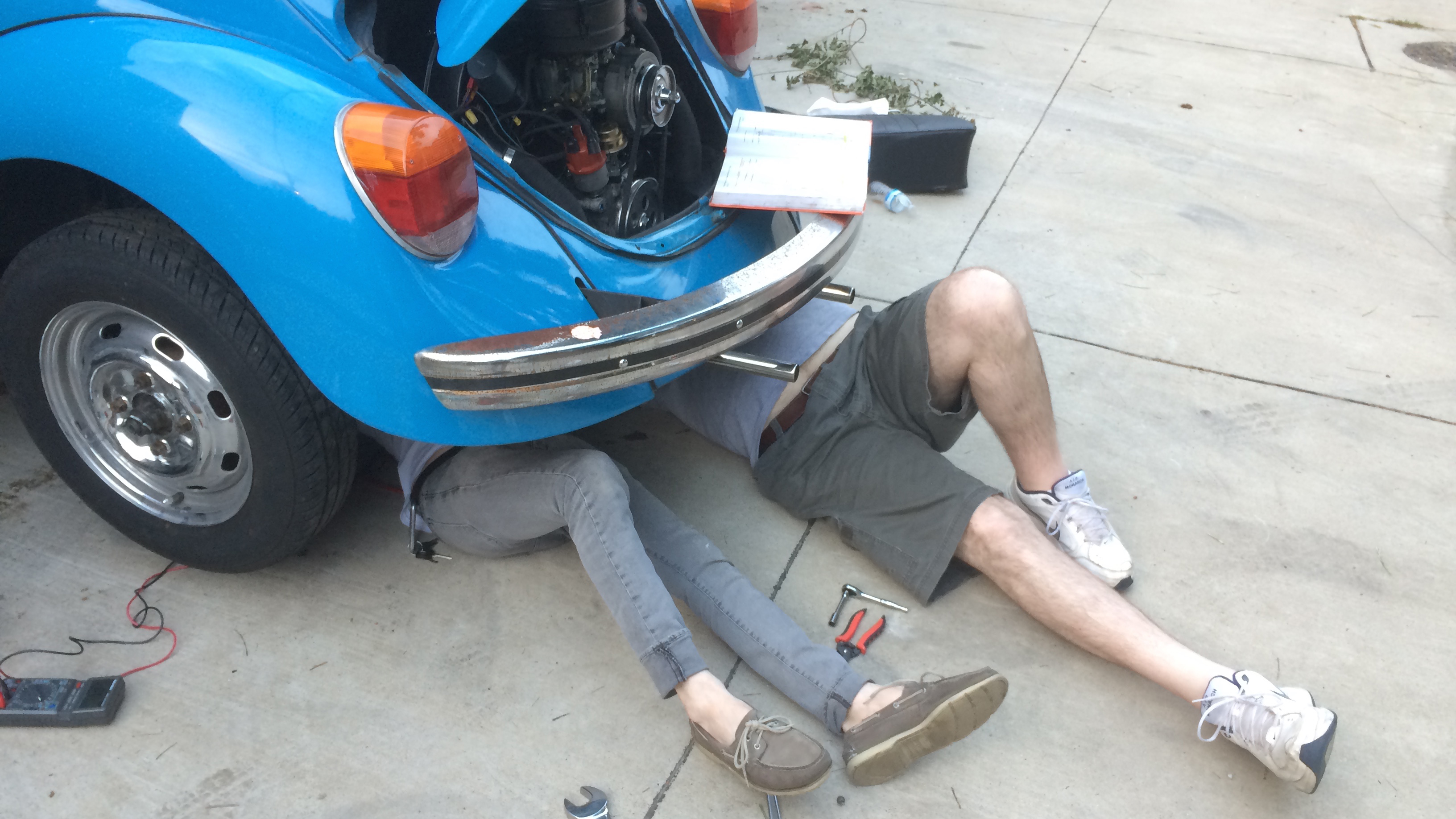
My dad was generous (and crazy) enough to drive the car up to me in Baltimore on a U-Haul car carrier a week later so he could retrieve his car, which I had drove up from Atlanta. We completed the final work on the car out of a garage which is included in the apartment I'm subleasing. This included connecting the braided steel tubes to the external oil filter, connecting a few electrical components in the engine bay (alternator, fuel cutoff solenoid, electric choke, coil and oil pressure sender), and connected the starter. We even met a new friend, Noah, who I saw driving his E30 BMW through the garage area and gave the cool car head nod to. He came over and helped my dad and I sort out the starter wiring.
At this point, we filled the car with oil, put some gas in the tank, adjusted the static timing (timing at full-advance can't be adjusted until the engine is running), and set the point gap. As mentioned earlier, the engine was cranked without the spark plugs inserted until the oil pressure light turned off, which ensures that oil has circulated throughout the engine. After this, the spark plugs were torqued down and the engine started right up! We followed the break in procedure outlined in the book, a procedure which is highly disputed, it involved running the engine at a constant RPM for about 20 minutes. At this point the car was ready for a drive. You can see a video of the first startup here, along with my excited / sweaty face. Also in the video you can see the timing light I used to set the full advance timing and a tachometer temporarily wired to the ignition coil in order to maintain the RPM outlined in the break-in procedure. After this, an oil change was done to clear out any of the metal particles generated during the break-in process. Also in this first oil change, the lifter lapping compound is mostly cleared out of the engine. After the engine cooled, the valves were adjusted again, and then the car was ready to drive! I've been driving the car very rough these first few hundred miles, in order to break the piston rings in. I followed Clyde's advice and basically put the car through repeated cycles of full-throttle accelerations and hard engine braking.
The car was initially running very rough and it was impossible to fix, which made me very concerned. I made sure all of the tune-up items were in perfect order, mainly point gap, and spark advance, and I just couldn't get the gremlins out. The idle was very rough, and the car didn't want to maintain speed on the highway, really heartbreaking stuff after putting so much work into it. I left the car at work overnight after my drive to work one morning was particularly rough and returned the next day with more tools. Stabbing in the dark I decided to use an automotive meter to set the dwell angle, instead of setting the point gap. The dwell angle is the number of degrees that the distributor shaft turns between when the points close and when they open again, which is directly related to the gap that would be set when the points are in their "full open" position. I was getting very inconsistent and erratic measurements on the meter. The number was dancing around on the meter, and the adjustment of the points gap, bigger and smaller, had almost no correlation to the new reading on the meter. I was at a loss, until I removed the points for inspection to find that one of the contact points on the arms of the point assembly was completely missing.
One set of new points and a timing adjustment later, and the engine was idling smooth as butter and running like a dream. I couldn't be happier. Honestly, this has been one of the most challenging, scary and fun things I've ever done. It felt like every day of work had a new hurdle to jump over, but the payoff has been pretty incredible. I'm so excited that my bug is back on the road and I'm finally able to drive my car again. Unfortunately now, since I'm now 100% responsible for the engine and its maintenance, if I'm ever stranded I only have myself to blame, which should be interesting. Hopefully though, with consistent maintenance (and love and care) the engine continues to treat me well for years to come. Send me an email if you have any questions about the process and I'll be willing to help you in any way I can!