05/5/2015
engine stand adapter plate
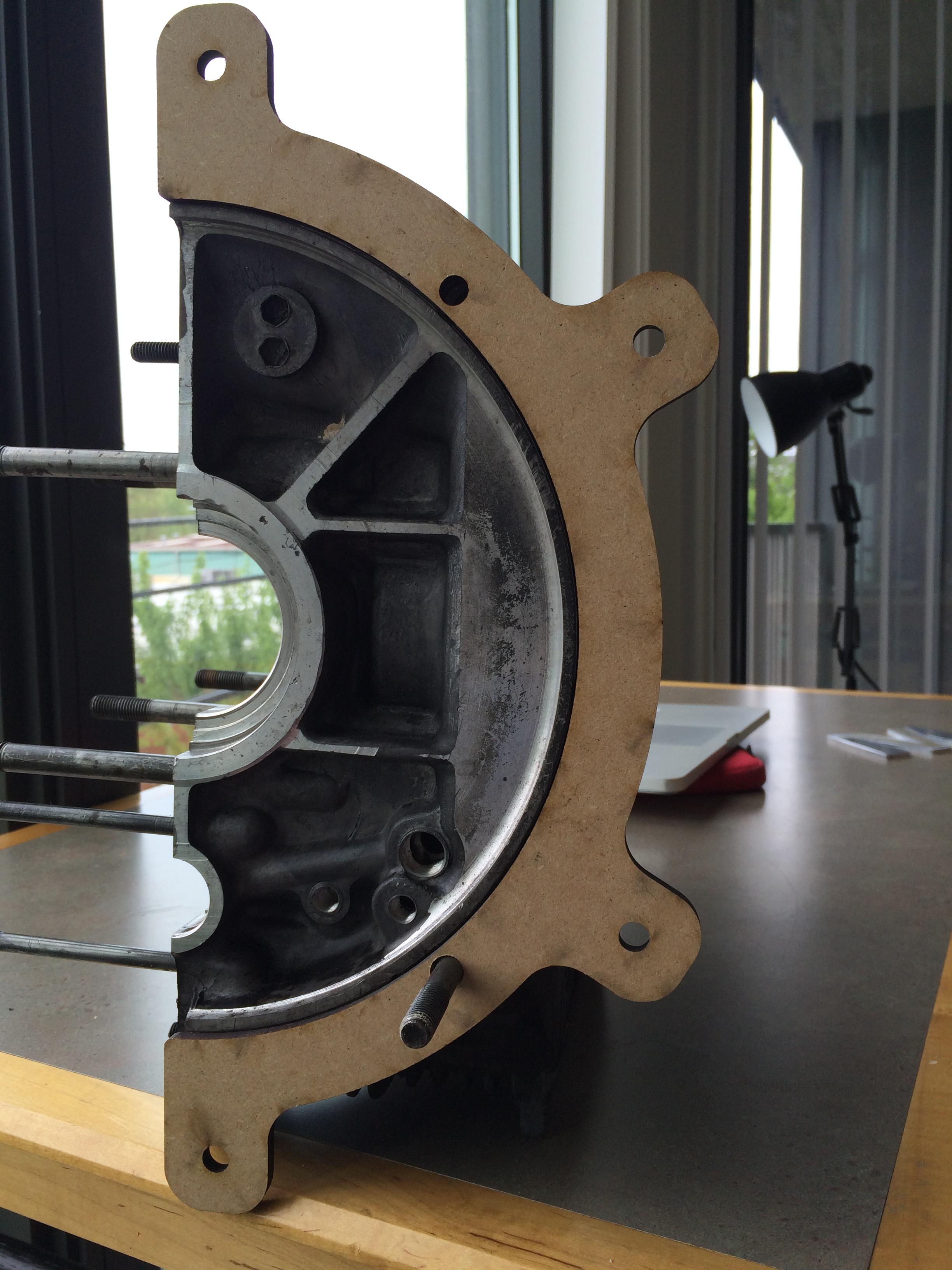
I'm getting ready to rebuild my VW's Type-1 engine, and as mentioned in the last update, it doesn't exactly fit on my engine mount. If you're interested more about the problem itself and some of the thinking process, you can read the thread I started on The Samba (a popular Volkswagen forum) from when I was taking it apart. Essentially, the engine stand I bought was too big to fit onto my engine. Additionally, the tubes that hold the mounting bolts captive have a pretty large diameter, and if they were fitted directly to the flange on the rear of the engine I feared they would marr the surface or make a gouge. The engine isn't that heavy, but I figured it couldn't hurt if I had something that fit around the radius of the flange to provide extra leverage. This would also allow for all four fingers on the engine mount to be used for extra security.
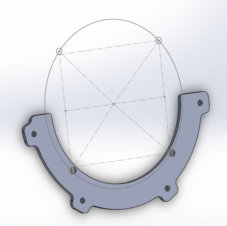
It took some iteration with my friend Austin, a certified ME guru. With some inspiration from the submissions on the fourm we came up with this prototype and cut it out of some particleboard to test the fitment.
Having some experience with the Solidworks constraint tools really helped here. It allowed us to measure the hole locations on the back of the engine using only a few dimensions that were easily measureable, leaving the rest for the constraint solver to figure out. I think we found (can't find it now...) another drawing somebody else had done and were able to verify that our dimensions were correct. Printing more wood prototypes allowed us to verify that.
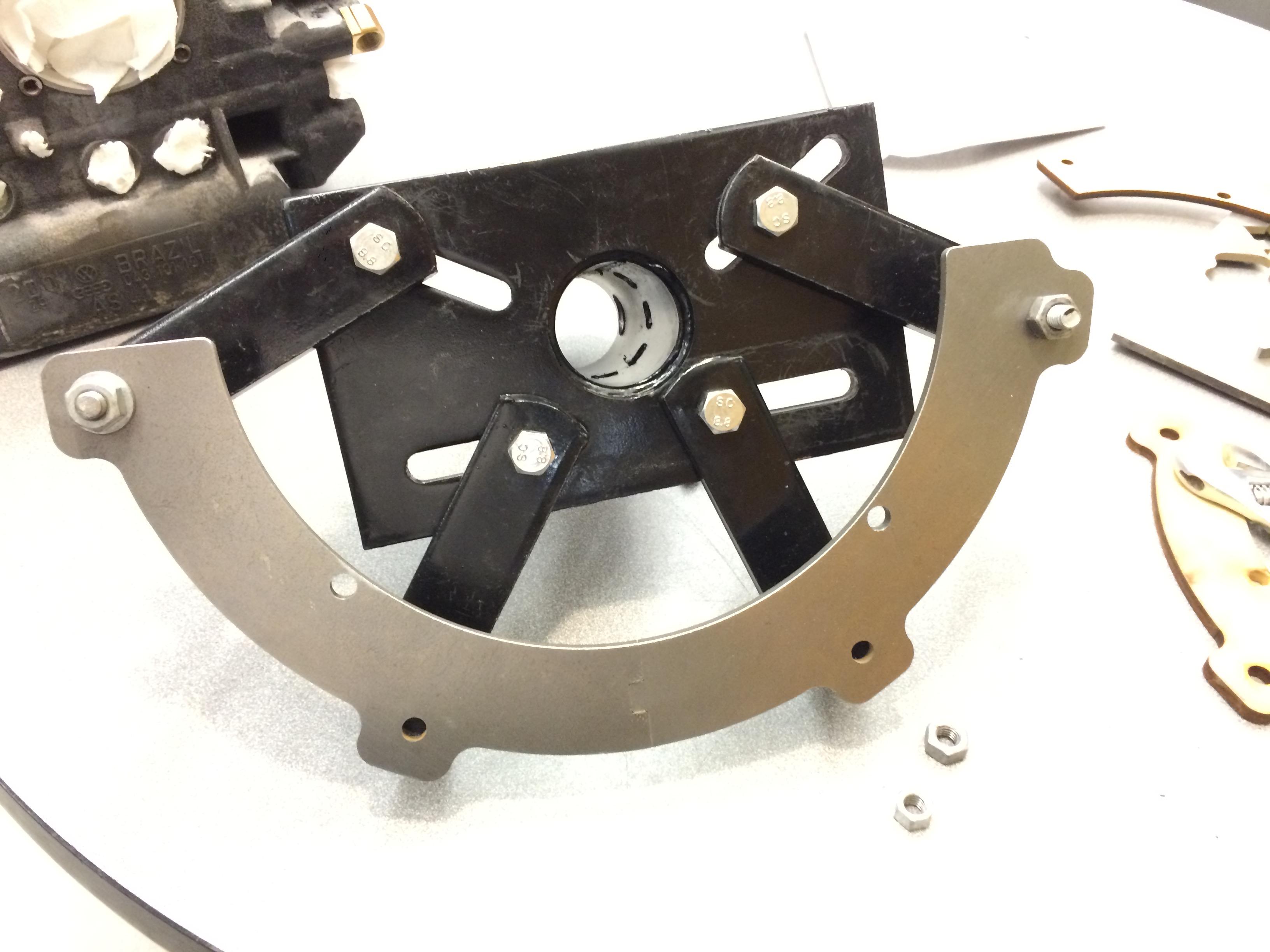
Obviously wood wasn't up for the challenge of holding the engine during assembly, so I ordered some quarter inch steel plate McMaster and picked it up at the will call. The adapter is quite large, so to save money, we split it in half, adding a little puzzle-piece cutout to align them with one another. This probably saved about $100, the smaller sheet cost about $45. A quick trip to the water jet later and the part was cut.
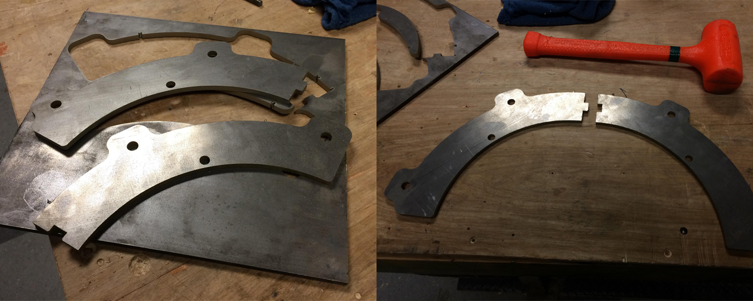
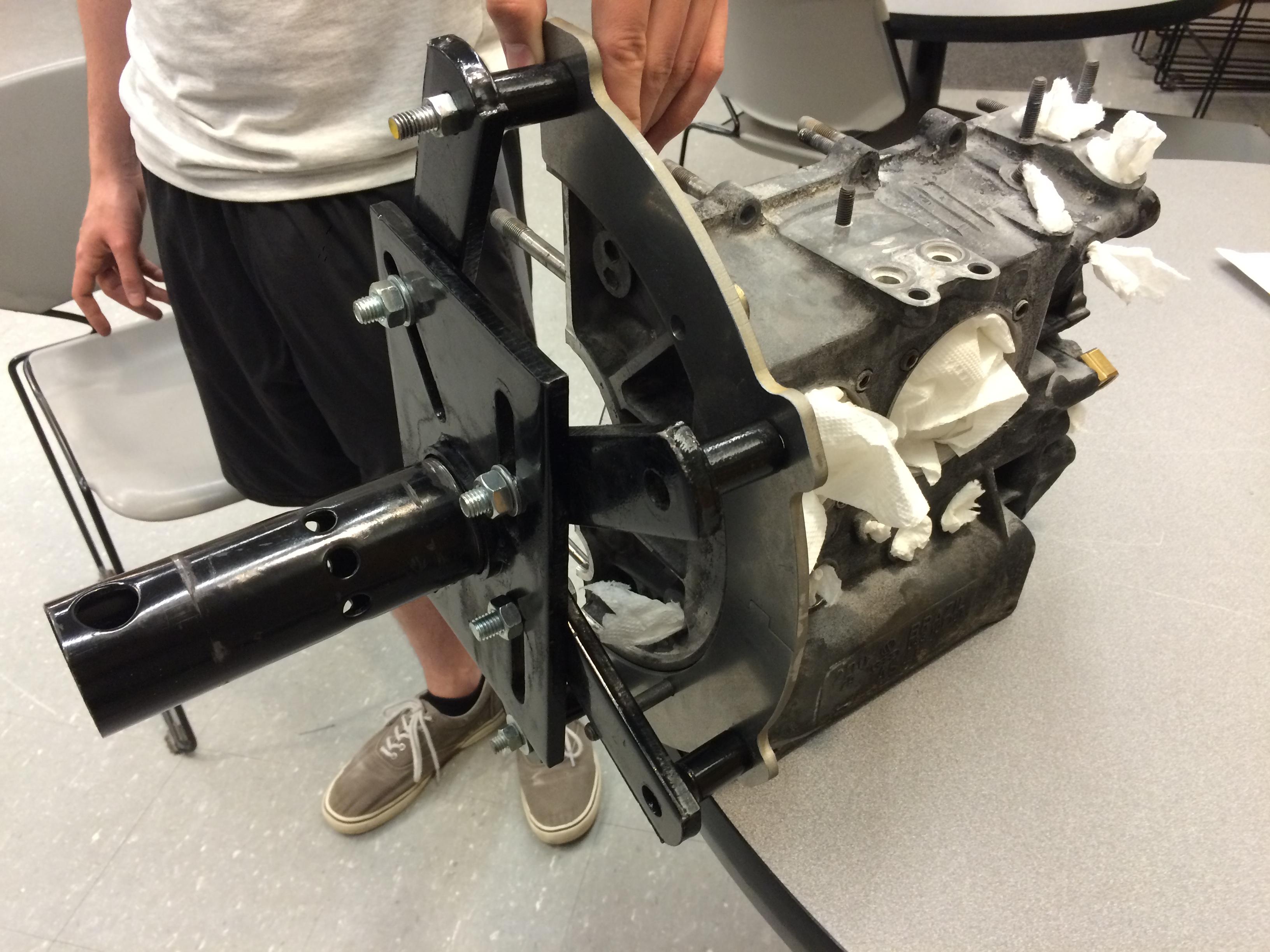
The tab attachment actually worked great. The water jet actually has a cut that expands a little bit as it goes through the metal (due to the water and garnet material spreading out in a cone shape) so the two pieces pressed together snugly. If they hadn't, I think it would have been fine, because each half is held to the engine mount by two fingers. After a quick trip to the bench grinder to soften up the edges, this is what the adapter looks like attached to the mount, and with the engine attached (with a little cameo by Austin).
04/25/2015
solidworks learning process
I've wanted to learn Solidworks for a while now. Obviously not going to be a total power user anytime soon, but I wanted to know enough to be mildly dangerous. I'm about to rebuild my Volkswagen's engine and while doing the teardown last semester I discovered that the engine stand I bought is just too big to fit the engine on. It's geometrically impossible to align the fingers with the holes on the back of the engine case. Even if I could, the fingers are large tubes that would dig into the flange on the back of the engine. I want to make something to adapt the two. My friend is helping me along the way, but I would like to do the final design.
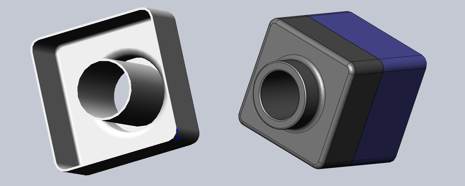
Solidworks is provided to Georgia Tech students for free. A slightly painful install later and things were up and running. I was actually pleasantly surprised to find the included tutorials. I walked through the first four or five and made the various items they had to model. I found the constraint system to be really intuitive coming from Cocoa/UIKit's autolayout system, things made pretty good sense. The tutorials also were in a really natural order. You learn extrusions and extruded cuts first, which helps teach the sketch tools. With these you build a simple little box using the shell tool and finish things up with the fillet tool. The first tutorial also teaches how to make assemblies.
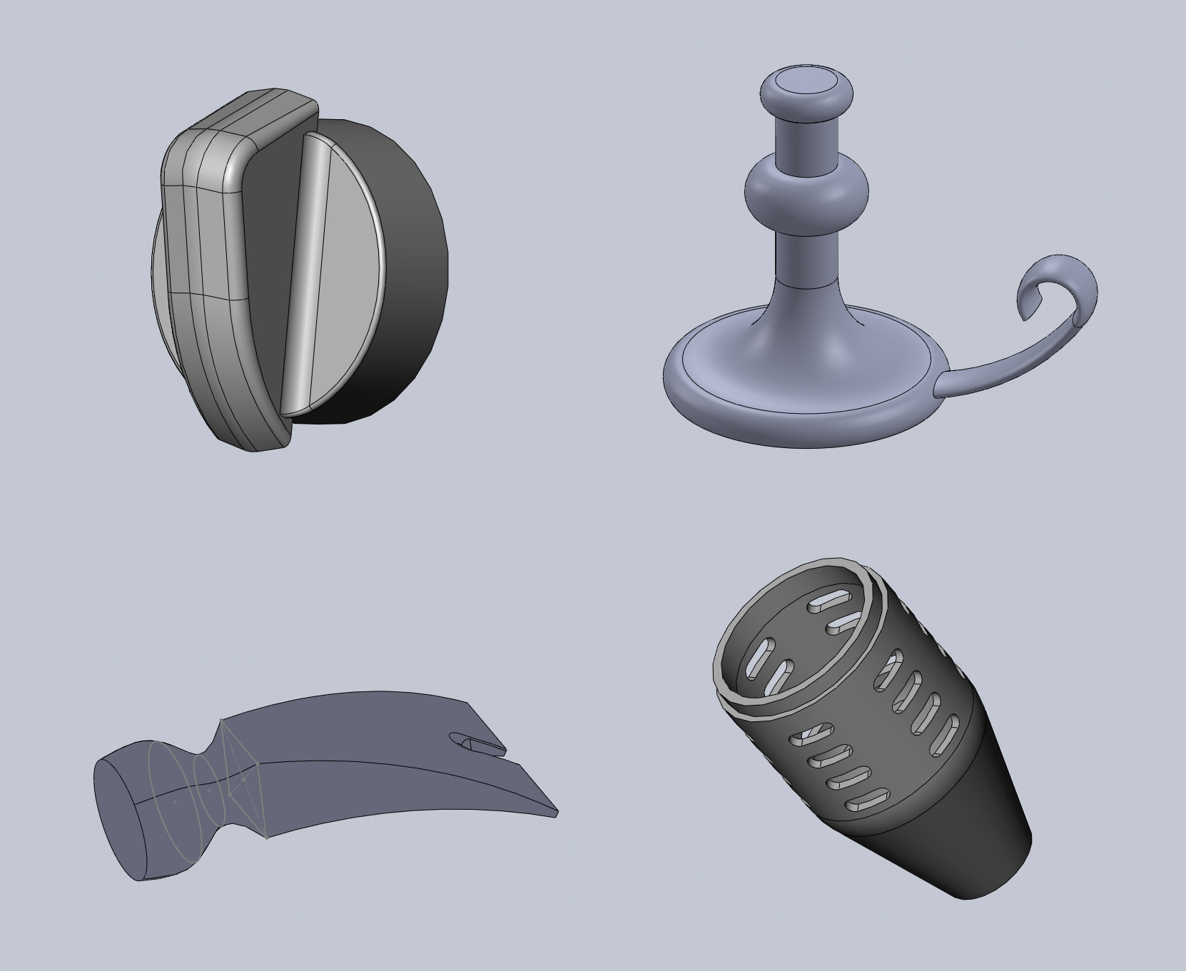
The next part teaches drafts and mirroring to make a little knob, it also introduces some more complicated uses of the fillet tool. The candle holder introduces revolving and sweeping. The hammer head introduces lofting. The torch (I think?) tutorial shows how to use equations to drive the sketch, the number of cutouts can be changed using an equation in the equation editor.
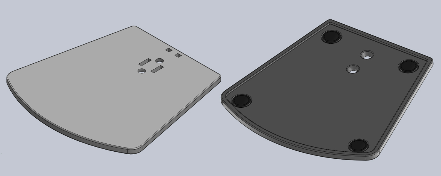
After walking through some of the tutorials to get comfortable I wanted a bit of challenge, so I looked around on my desk for something simple I could replicate. I have this little Bose speaker and I thought it would be a good challenge. I didn't get all the way through it, but I managed to replicate the base and the rubber feet before deciding I needed to get onto a real project. I really should finish it in the future, I think the stem would prove a good challenge with it's interesting angles.
04/20/2015
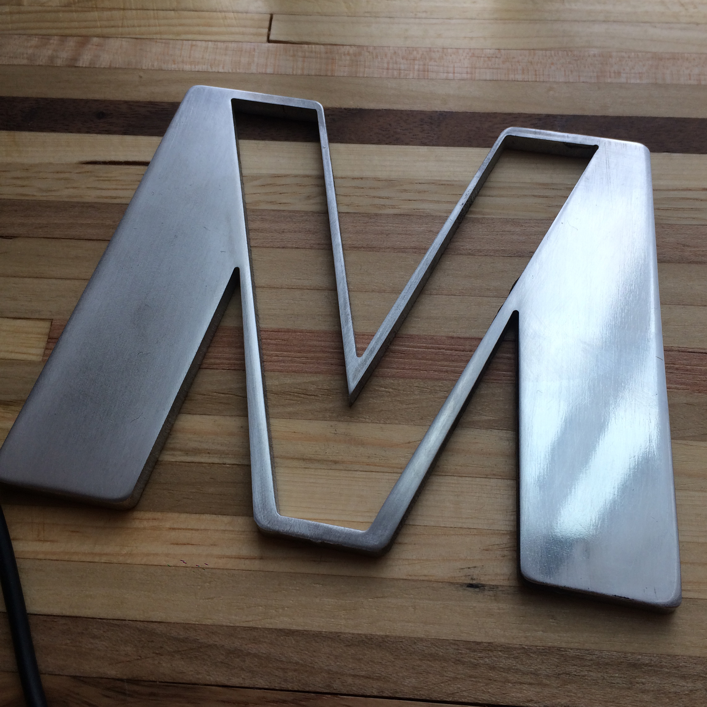
waterjet anniversary gift
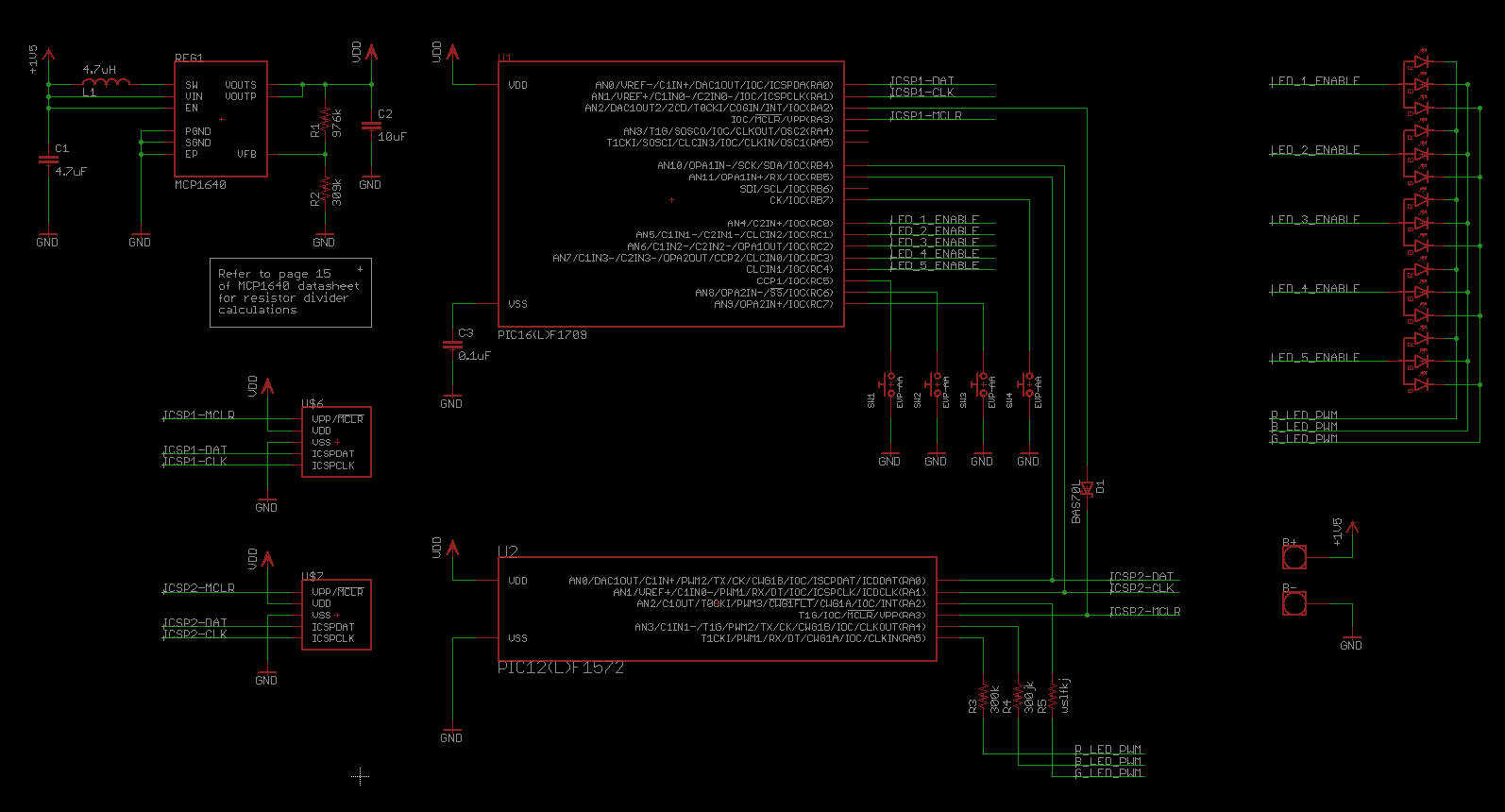
My girlfriend and I are celebrating our one year anniversary, so I wanted to make her something kind of special. I had this idea of placing her first initial, V, inside my first initial, M. The ambitious part of me wanted to make some sort of necklace with a V-shaped hole in the M, with a small PIC that controlled a few RGB LEDs. The circuitry was pretty simplistic, the only novel idea I had was using two microcontrollers in a master/slave configuration. A PIC16 dealt with the four button inputs and controlling the five LED enable lines. A secondary 8-pin PIC12 connected via SPI did the PWM to control each LED's brightness. There was probably a better way, but our anniversary was quick approaching, and haste makes waste they say.
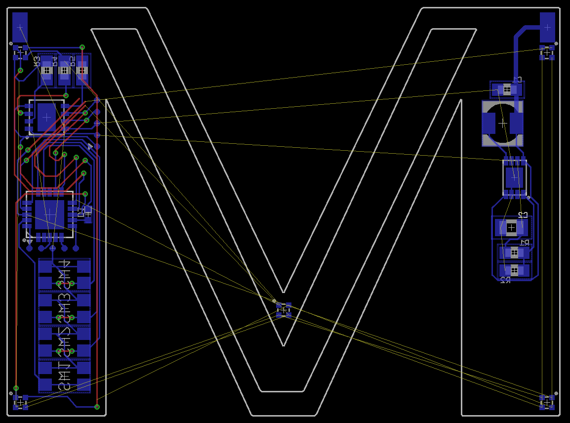
The battery was mildly tricky, I was planning on powering it from a small triple A or coin cell in the clasp behind the neck. The chain would actually carry some small current down to two pads on the top left and top right of the board. The idea was that just connecting the chain in the back would complete the circuit and turn the necklace off and on.
Routing is where this all fell apart. Even on four layers I just couldn't get the shape of the M and the V to be very pleasing and also have enough room to route everything down the remaining board area. Eagle was a pain here, the time it takes to import something from Illustrator (where creating desirable shapes is a somewhat pleasant experience) into Eagle and get the scale right is a huge barrier. Importing bitmaps is easier, since the ULP creates this solid shape out of lots of skinny polygons, but it's more painful when you actually want to import a shape to use as the boundaries of a polygon. Keep in mind here that the necklace was only going to be about 1.5x1.5 inches. Probably too small a goal for a two week project.
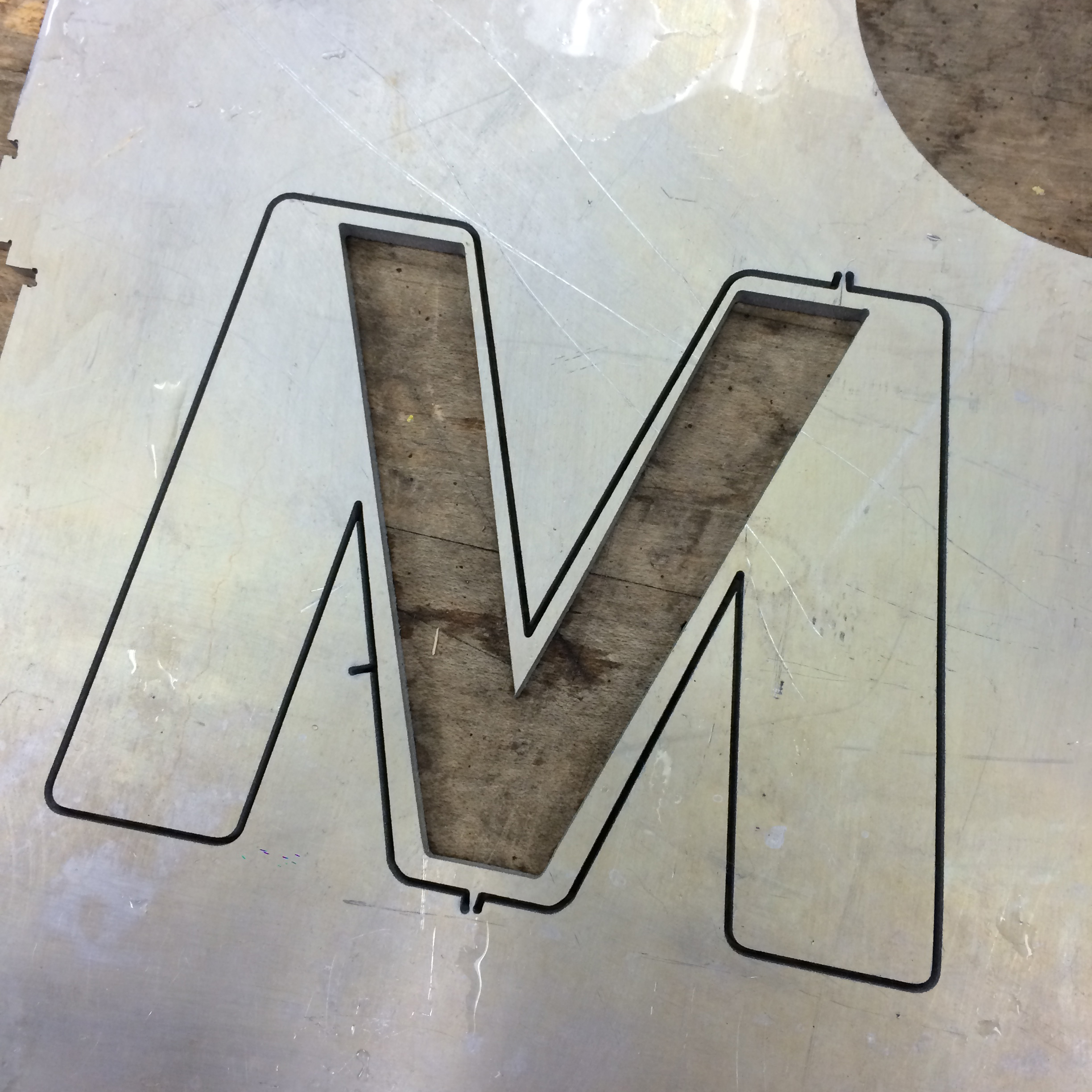
plan b
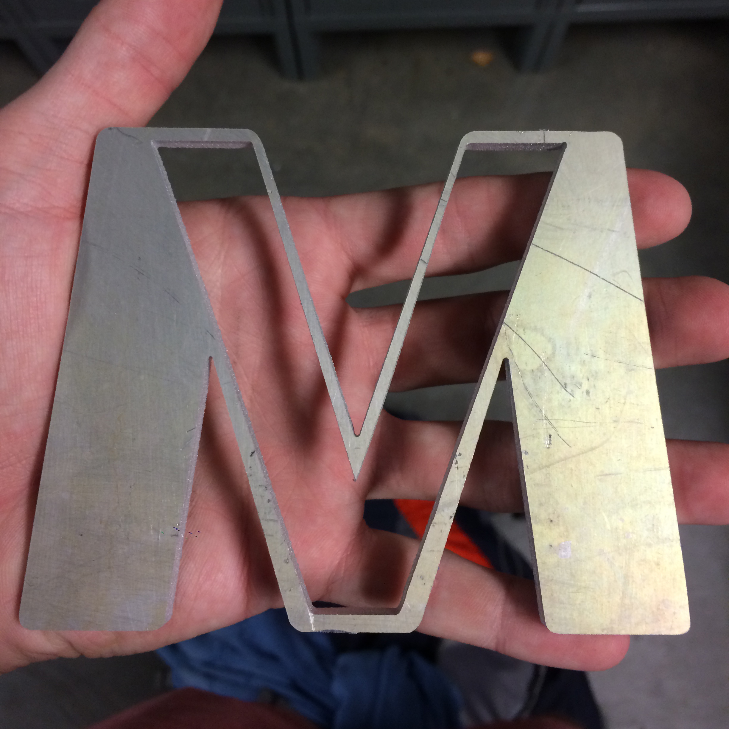
I had been looking for an excuse to learn how to use the water jet in Georgia Tech's Invention Studio, and my friend had some spare aluminum sheet he wasn't using, so I figured I could adapt the shape and still make a nice memento. I drew up the design in Illustrator, having a little more fun with making the letters pleasing, since I didn't have to worry too much about the board material or the capabilities of OSHPark. After the drawing was done it was quick work to get it carried over into the OMAX's software as a DXF. The machine in the shop can cut through inches of steel and granite so it didn't have too much trouble with the quarter inch aluminum plate.
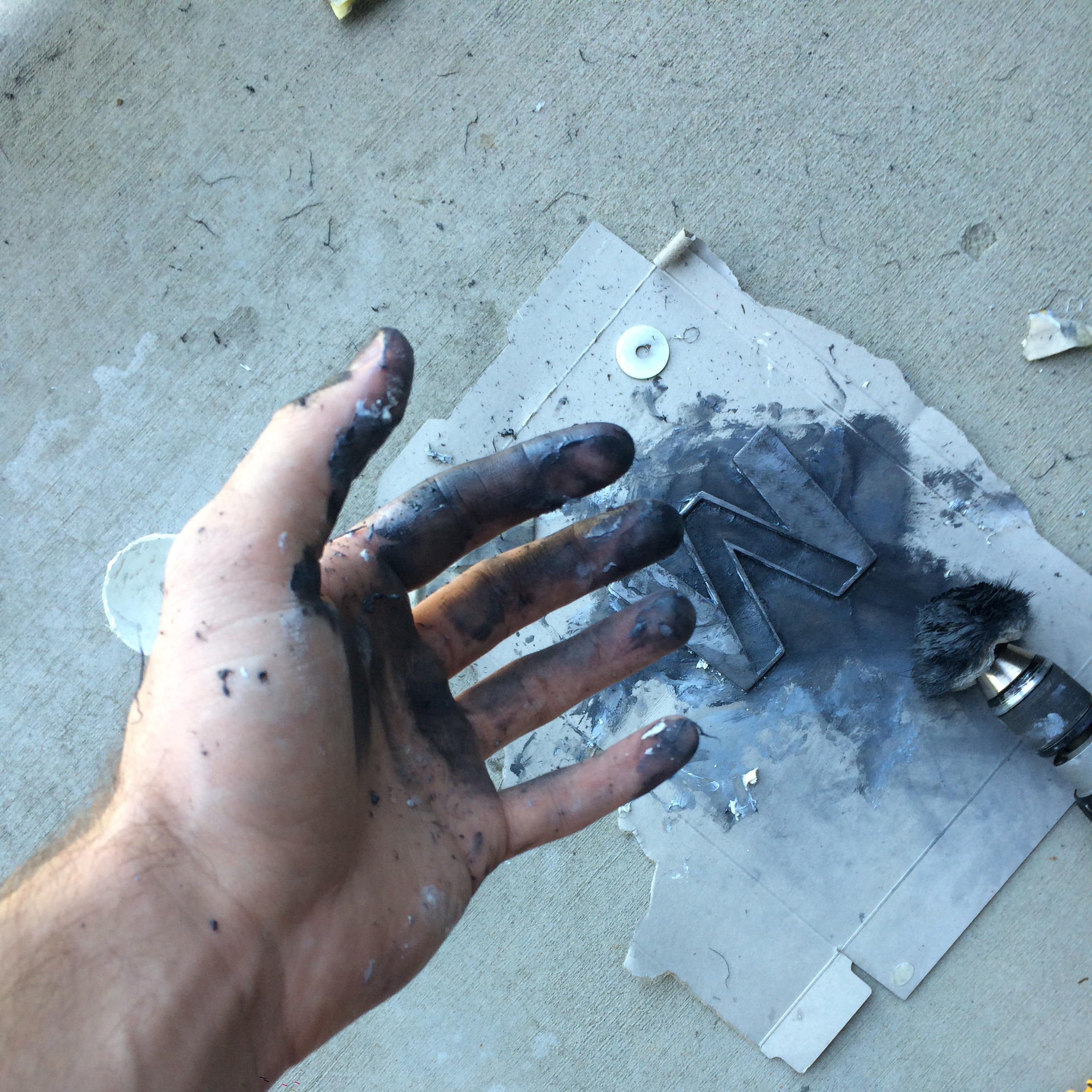
I put a lot of elbow grease into polishing it. I think the aluminum I used wasn't very high quality, so I kept hitting little pores that needed more sanding. I started with really rough sandpaper and gradually worked up to some stuff I got at the auto parts store intended for wet sanding. After wet sanding I got tired of ripping my fingers to shreds so I bought a drill-mount polishing wheel. I tried various types of silver/metal polish until I found something that worked relatively well.
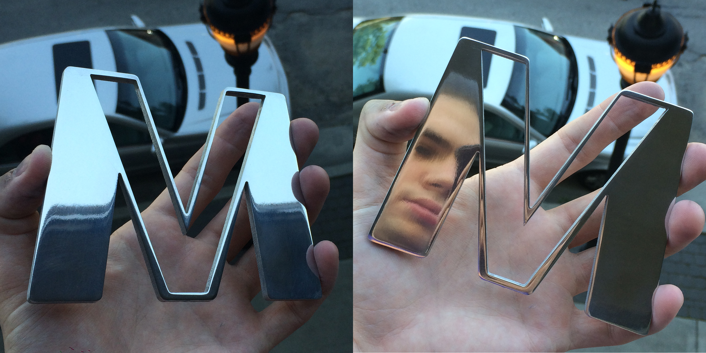
Looks pretty nice on the desk too. Kinda bummed it doesn't light up, but I think she likes it and I had lots of fun making it.