Just a quick update on the VU meter clock.
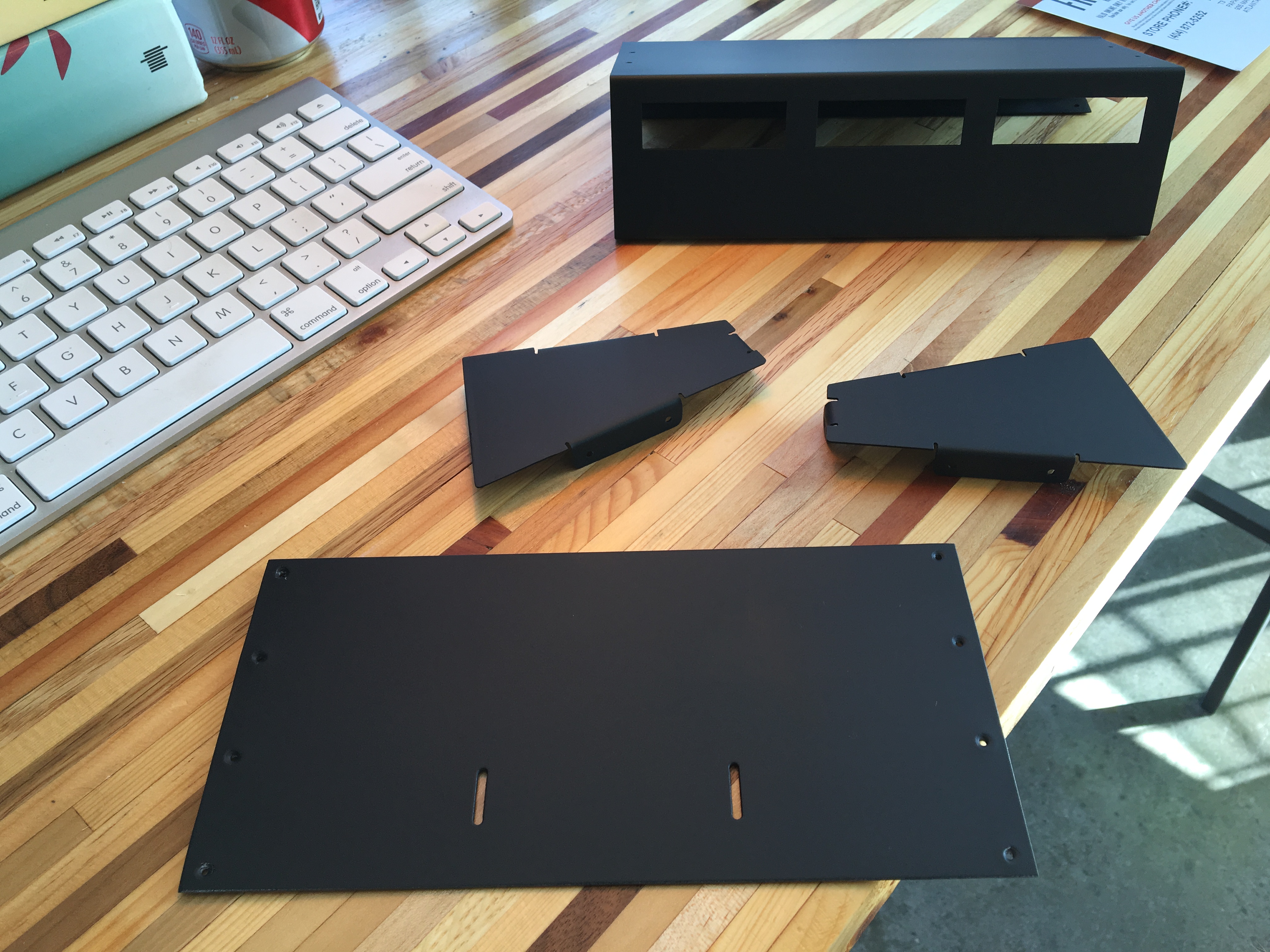
I got around to painting it the other day. The matte black (just the cheapest plain Rustoleum cans) came out incredibly well. In fact, I don't think I've ever had a paint job come out this well.
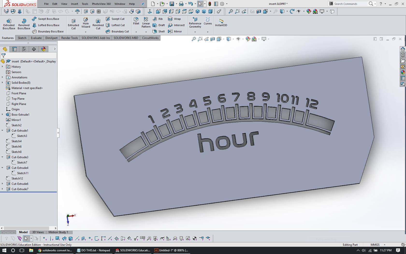
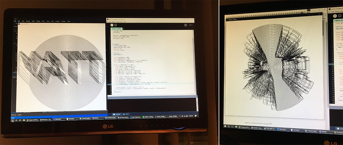
I've also been working on the new designs for the meter readouts. I tried to do this in illustrator, but I wanted to position text accurately against an arc, and I was having a really difficult time of making it precise. I figured I already had a model of the meter in Solidworks, so why not do it there. So that's what I did. This sketch is horrendous, but it worked great.
The final project in my embedded systems class is to come up with a project for yourself. I've been fairly busy the last few weeks as the Fall semester was entering the final push, so I haven't been able to work on much other than classwork. But this is classwork! In reality, this was a group project, but I did most of the work here other than some paperwork that was required, so here's what I did.
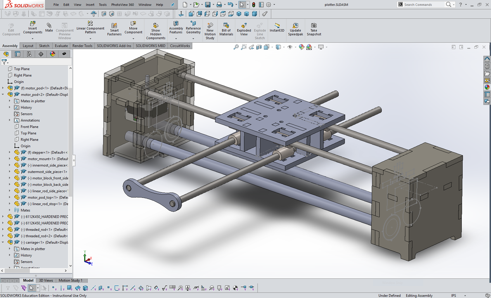
I actually had two identical printers that I discussed in my printer carriage reverse engineering entry and I thought I could make an XY pen plotter from them. I spent a lot of time deliberating how I was going to make everything come together, originally planning on some insane laser-cut jigs and 3D printed pen actuation systems. I was considering placing one carriage on the top or bottom and one carriage on the left or right of the drawing surface, and then using static rails opposite the carriages to support the X and Y rods. This would have probably been the most stable solution, but would have required more fabrication that I had time for. After remembering videos of Evil Mad Scientist's AxiDraw (they actually released V3 while I was working on this) I felt I could recreate the concept with two carriages. Realizing I wouldn't have enough time to do anything super complicated, I reached for some aluminum bar, a Dremel, and some bolts and nuts that I had laying around and got to work.
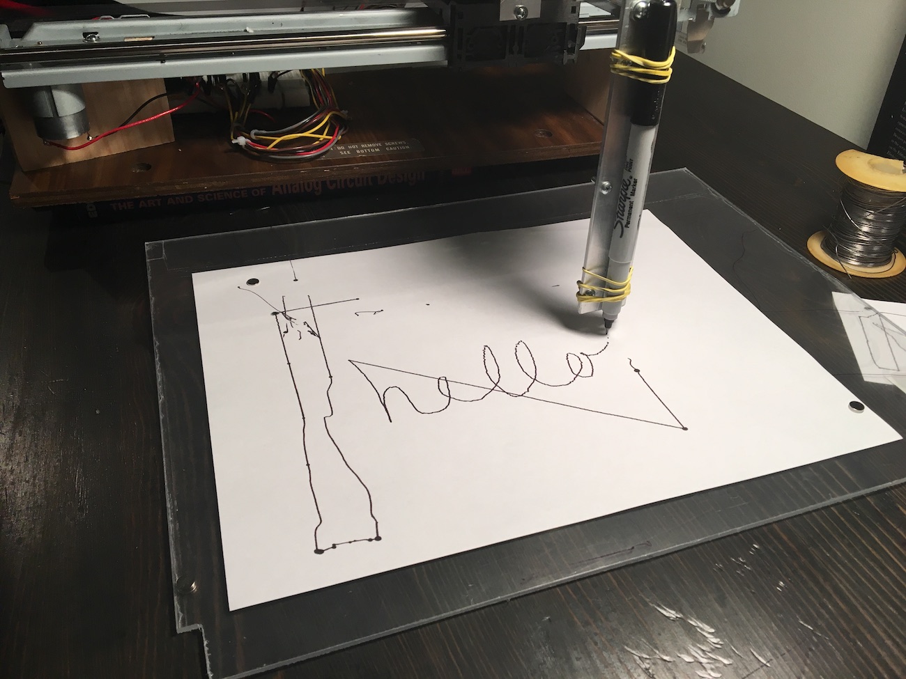
Here's a teaser image to show what was accomplished. There's a lot of implementation detail that's covered here, if you're more interested in the end product (which I think is pretty neat) skip to the bottom to check out some videos and future ideas I have about the whole thing.
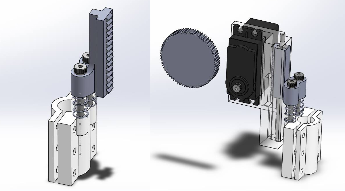
rejected pen lift mechanism
I also decided to not have the pen lift up and down. Here's some concepts I had for a servo-driven pen lift mechanism, but I was spending too much time on this than the core functionality, and getting access to 3D printing time late in the semester can prove a challenge. My novel thing here was that the pen holder was spring loaded, so the servo would be controlling the vertical position of the pen as well as the spring pressure placed on the tip of the pen. This would allow the servo to push the pen "into" the paper. This way the exact Z-height of the paper and tip would not be super critical, and the pen would stay contacted with the paper even if the paper was slightly non-level.
making it 2D
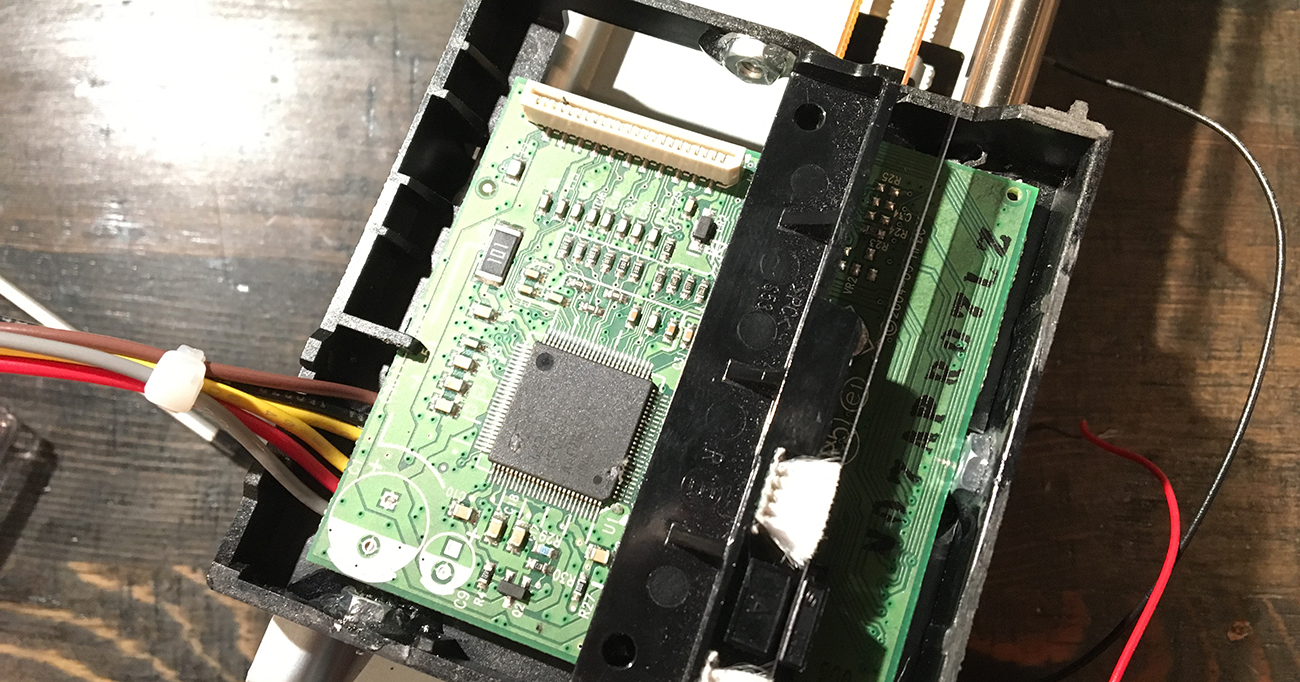
To copy the AxiDraw, my idea was to just connect the two carriages to one another at a 90 degree angle. This means one carriage would have an entire second carriage assembly riding on it. To do so, I cut off a lot of the extraneous plastic on the carriage that would normally be holding the inkjet cartridges. I roughly cut some aluminum bar (metalworking in a city apartment is a little dicey) to attach the two together. I got really lucky that the circuit board housing was roughly square. I had a little trouble getting access to some of the nuts that were on the second plastic piece, so I epoxied those in place.
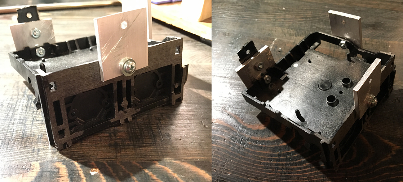
With an afternoon of hacking on it, I got it all back assembled and able to move in X and Y by hand, which was fairly exciting.
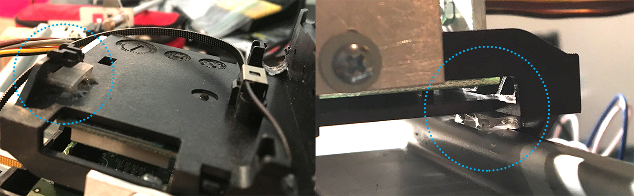
The carriage had a lot of play in it (the plastic piece could move up and down on one half of the metal rail). I can't think of any reason this was in the original design. My only thoughts were that the weight of the inkjet cartridges out on their mounts kept the carriage from ever rotating, and the rotation facilitated rubbing the print heads up on some sort of cleaning brush. The play made the second arm of the assembly very wobbly, as just a degree or two of rotation of the main carriage meant many millimeters of vertical motion of the tip of the second arm. To fix this, I epoxied a piece of thin acrylic to the bottom of the first plastic carriage. This reduced the amount of slop in the system considerably.
motorized motion
With the driver code that was already written, it was relatively simple to control the second axis. Just a few more wires to connect and a few extra lines of code and it was moving in a rough circle. It wasn't super stable, but it was very promising.
adding a pen
With this success, I made up a little rubber-band pen holder to mount on the end of the second arm. I adjusted a few lines of code and thought I could get it to draw a circle. I was hilariously wrong.
serial control
Part of the requirements stated in the project guidelines was some sort of host application. The thought was to have a Windows app that controls the plotter, so I needed to create some standardized way to control the plotter over a serial port. I probably could have gone with gcode, but I decided to do something custom. What I wrote could actually parse gcode just fine, but instead of M* commands I used letters. Instead of having the parser and the application logic intertwined, I decided to write a parser that interprets the serial stream input and compares commands to a list of commands that have been registered at runtime. The parser then delegates the response to each command to the appropriate callback functions.
This was my first time writing a singleton in C++, so I'm not 100% I used best practices, but it got the job done.
class SerialCommander {

public:
    Serial _term;
    static SerialCommander *shared_instance;
    struct command {
        char *name;
        int param_count;
        void (*callback)(char argv[10][100], int);
    };
    int num_commands;
    command commands[100];
    int serial_buffer_size;
    char serial_buffer[100+(10*100)];

    //----- static member functions -----//
    SerialCommander();
    static SerialCommander *instance();
    static void static_serial_irq();

    //----- member functions -----//
    void register_command(char *name, int param_count, void (*callback)(char[10][100],int));
    void setup();
    void handle_serial_character();
    void handle_serial_command();
    void delegate_command(char *command_name, char argv[10][100], int argc);
    void send_response(char *response);
    void send_ack();
    void send_nack();
    void send_command(char *command_name, char argv[10][100], int argc);
    void send_return(char argv[10][100], int argc);

};
#include "SerialCommander.h"

SerialCommander::SerialCommander() : _term(USBTX, USBRX){}

void SerialCommander::static_serial_irq() {
    shared_instance->handle_serial_character();
}

SerialCommander *SerialCommander::instance() {
    if(!shared_instance) {
            shared_instance = new SerialCommander;
    }
    return shared_instance;
}

void SerialCommander::register_command(char *name, int param_count, void (*callback)(char argv[10][100], int)) {

    command new_command = {};
    new_command.name = name;
    new_command.param_count = param_count;
    new_command.callback = callback;

    commands[num_commands++] = new_command;
}

void SerialCommander::handle_serial_character() {
    while(_term.readable()) {
        char c = _term.getc();
        serial_buffer[serial_buffer_size++] = c;
        if(c == ';') {
            this->handle_serial_command();
        }
    }
}

void SerialCommander::handle_serial_command() {
    // wait until the first ! or ?, then the characters until a space
    // are the command name, next should be comma delimited parameters

    bool found_command_start = false;
    bool is_query = false;
    bool found_command_name = false;

    int command_name_size = 0;
    char command_name[100];

    int current_param = 0;
    int current_param_size = 0;
    char command_params[10][100];

    for(int i = 0; i < serial_buffer_size; i++) {
        char c = serial_buffer[i];
        if(found_command_start) {
            if(found_command_name) {
                // if this is a command, not a query, then we need to parse
                // all of the params, if it's a query, go ahead through the
                // list to exhaust the buffer (inefficient, but works for now)
                if(c != ';') {
                    if(!is_query) {
                        if(c == ',') {
                            command_params[current_param][current_param_size++] = '\0';
                            current_param++;
                            current_param_size = 0;
                        } else {
                            command_params[current_param][current_param_size++] = c;
                        }
                    } else {
                        continue;
                    }
                } else {
                    if(!is_query) {
                        command_params[current_param++][current_param_size++] = '\0';
                    }
                    break;
                }
            } else {
                if(c == ' ' || c == ';') {
                    found_command_name = true;
                    command_name[command_name_size++] = '\0';
                } else {
                    command_name[command_name_size++] = c;
                }
            }
        } else {
            if(c == '?' || c == '!') {
                found_command_start = true;
                is_query = c == '?';
            }
        }
    }
    this->delegate_command(command_name, command_params, current_param);
    serial_buffer_size = 0;
    command_name[0] = '\0';
}

// looks through the command list and calls the right callback
void SerialCommander::delegate_command(char *command_name, char argv[10][100], int argc) {

    for(int i = 0; i < num_commands; i++) {
        command current_command = commands[i];
        if(strcmp(current_command.name, command_name) == 0) {
            current_command.callback(argv, argc);
        }
    }
}

void SerialCommander::send_command(char *command_name, char argv[10][100], int argc) {
    _term.printf("!%s ", command_name);
    for(int i = 0; i < argc; i++) {
        _term.printf("%s", argv[i]);
        if(i < argc - 1) {
            _term.putc(',');
        }
    }
    _term.putc(';');
}

void SerialCommander::send_return(char argv[10][100], int argc) {
    _term.putc('!');
    for(int i = 0; i < argc; i++) {
        _term.printf("%s", argv[i]);
        if(i < argc - 1) {
            _term.putc(',');
        }
    }
    _term.putc(';');
}

// response must not have ! or ; or ?
void SerialCommander::send_response(char *response) {
    _term.printf("!%s;", response);
}

void SerialCommander::send_ack() {
    this->send_response((char*)"ack");
}

void SerialCommander::send_nack() {
    this->send_response((char*)"nack");
}

void SerialCommander::setup() {
    _term.baud(57600);
    _term.attach(static_serial_irq, Serial::RxIrq);

    num_commands = 0;
    serial_buffer_size = 0;
}

SerialCommander *SerialCommander::shared_instance = 0;
The code adds characters to a buffer as they are received and then attempts to parse the command after a semicolon is found. The idea here was that queries (starting with a ?) had no arguments, and were just to return some information (a current setting value, for example), and a command (starting with an !) had arguments. This ended up being of dubious use, but it's still in there anyway.
I think most of this code is pretty straightforward. Registering a command adds a command struct to an array. This struct holds the command name (so it can be identified when a command is parsed), the number of parameters expected, and a function pointer to call with the arguments that were sent with the command. When calling a callback, the arguments are placed into a 2D argument array, and then passed the number of arguments that were found when the command was parsed. Almost like how the C main function works.
In my main source code file, I register the commands like so:
void register_commands() {
    // heartbeat
    SerialCommander::instance()->register_command((char*)"h", 0, serial_heartbeat_callback);

    // get/set name
    SerialCommander::instance()->register_command((char*)"n", 1, serial_name_callback);

    // get/set position (does not move, just sets ref position)
    SerialCommander::instance()->register_command((char*)"p", 2, serial_position_callback);

    // get/set feedrate
    SerialCommander::instance()->register_command((char*)"f", 1, serial_feedrate_callback);

    // get/set positioning mode
    SerialCommander::instance()->register_command((char*)"pm", 1, serial_positioning_mode_callback);

    // move
    SerialCommander::instance()->register_command((char *)"m", 2, serial_move_callback);

    // move
    SerialCommander::instance()->register_command((char *)"rm", 2, serial_relative_move_callback);
}
Here's the rest of the main.cpp file, with some uninteresting function bodies removed.
#include "mbed.h"
#include "DebounceIn.h"
#include "PrintHead.h"
#include "SerialCommander.h"
#include "Ticker.h"

// stores the name of the printer here
LocalFileSystem local("local");

PrintHead y_head(p13, p14, p26, p15, p16);
PrintHead x_head(p11, p12, p25, p17, p18);

enum positioning_mode {ABS, REL};
enum positioning_mode current_positioning_mode = ABS;

int feedrate = 600;
int update_rate = 500; //Hz
int x_goal = 0;
int y_goal = 0;
float d_x_tick = 0;
float d_y_tick = 0;
int traverse_timer_total_ticks = 0;
int traverse_timer_current_tick = 0;
bool should_move = false;
bool traversing = false;

Ticker move_ticker;

void move_tick() {
    if(should_move) {
        if(traverse_timer_current_tick++ == traverse_timer_total_ticks) {
            should_move = false;
            SerialCommander::instance()->send_ack();
        } else {
            x_head.goal += d_x_tick;
            y_head.goal += d_y_tick;
        }
    }
}

void initiate_move(int end_x, int end_y) {
    int d_x = end_x - x_head.count;
    int d_y = end_y - y_head.count;
    float dist = sqrt((float)(d_x * d_x + d_y * d_y));
    float traverse_time = dist / feedrate;
    traverse_timer_total_ticks = update_rate * traverse_time;
    traverse_timer_current_tick = 0;
    d_x_tick = d_x / (float)traverse_timer_total_ticks;
    d_y_tick = d_y / (float)traverse_timer_total_ticks;
    should_move = true;
}

void serial_heartbeat_callback(char argv[10][100], int argc) {}

void serial_name_callback(char argv[10][100], int argc) {}

void serial_position_callback(char argv[10][100], int argc) {}

void serial_positioning_mode_callback(char argv[10][100], int argc) {}

// sets the feedrate in ticks/second, or returns the current feedrate
void serial_feedrate_callback(char argv[10][100], int argc) {}

void serial_move_callback(char argv[10][100], int argc) {
    if(argc == 2 && !traversing) {
        int x = atoi(argv[0]);
        int y = atoi(argv[1]);
        if(current_positioning_mode == ABS) {
            initiate_move(x, y);
        } else if(current_positioning_mode == REL) {
            initiate_move(x_head.count + x, y_head.count + y);
        } else {
            SerialCommander::instance()->send_nack();
        }
    } else {
        SerialCommander::instance()->send_nack();
    }
}

void serial_relative_move_callback(char argv[10][100], int argc) {
    current_positioning_mode = REL;
    serial_move_callback(argv, argc);
    current_positioning_mode = ABS;
}

void register_commands() {}

int main() {
    y_head.kp = 0.08;
    y_head.ki = 0.0005;
    y_head.kd = 0;

    x_head.kp = 0.08; //was 0.1 before ki added
    x_head.ki = 0.005;
    x_head.kd = 0;

    SerialCommander::instance()->setup();
    register_commands();
    move_ticker.attach(&move_tick, 1/(float)update_rate);
    while(1) {

    }
}
I left the most interesting parts in. The full source code is available here on my github. The command set allows for setting a feedrate, which controls how fast the pen moves. Since the feedback mechanism on the printer carriage is position, not velocity, I had to interpolate a number of points between the current position and the desired position to control the speed. This is done with initiate_move.
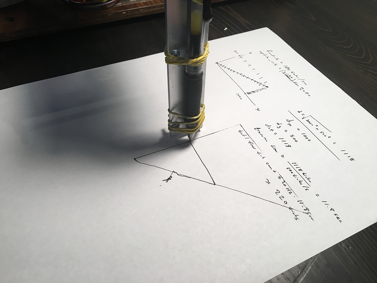
The function first calculates the total distance (all in ticks, since I didn't feel it necessary to know how many ticks per inch there was on the encoding strip) to the new location and uses the feedrate to calculate the total amount of seconds it should take to travel to the new location. There is a timer running at 500Hz which is used to update the goal position of each print head, so I use this frequency to calculate how many timer ticks it should take to complete the motion. Lastly, the number of ticks that the goal positions should be incremented by on each call of the timer method is calculated by dividing the X and Y distances by the number of total timer ticks needed to complete the move.
Each time the timer callback is executed, the X and Y goal positions are incremented by their corresponding increments. When the total needed number of timer ticks has been completed, an ack is sent to the host, which notifies the host of the completion of the move. I considered using a polling based model, but deemed this was simpler. The main() method ends up being beautifully simplistic since everything is somewhat reactive in nature.
Here's our first successful triangle that was plotted by issuing commands over the serial port. I was super excited when the pen ended right back where it started, even when drawing a larger triangle around the first.
WinForms app
The second part was building a program to interface with the plotter, which I think came out quite nicely. Before I get into this, here's a quick video showing the "workflow" that the app leads you through.
At the moment, the app lets you create either a spirograph or a single-line drawing (since the pen can't be retracted) to plot. Before plotting, the app lets the user move the pen to the top left and bottom right of the rectangle that they wish to bound their drawing into. The app then scales and translates the drawing into those bounds. This lets the user plot the spirograph say, over the entire sheet of paper or jut in a small box in the middle of the paper.
draw control interface
I used a (very simple) C# namespace to allow for any number of drawing "controls" to be drawn into the main window. The interface has one requirement, a method that returns a List of points. This means that I could easily create a new "circle" drawing tool with controls to adjust the circle radius and line width (maybe by doing a rectilinear fill on the border) and it could be placed into the main window and be plotted with no problem.
namespace XYPrinterController
{
    interface DrawControl
    {
        List<PointF> getPointsToPrint();
    }
}
spirograph control
I created a custom control that draws a spirograph into itself. Pretty much using the math outlined here on Wikipedia. This is my first time really doing anything more than a "hello world" with C#, so there was a lot to get used to. I had a hard time balancing my time between researching C# and WinForms best practices and actually writing code. The only real interesting thing I did here was scale the spirograph to fit inside the bounds of the control. Different parameters for the spirograph will generate different sized drawings, so I had to re-scale them.
If I had the time, I would have derived the "time" parameter when the spirograph will start retracing itself, so I don't waste time drawing too many line segments (or not draw enough to capture the full image). This would require solving the parametric equations, x(t) and y(t) to find for which value of phi x(t) = x(t + phi) and y(t) = y(t + phi). Maybe a future change.
The control itself has public variables that allow for the adjustment of the spirograph, but does not deal directly with user interaction to change these parameters.
using System;
using System.Collections.Generic;
using System.Drawing;
using System.Windows.Forms;

namespace XYPrinterController
{
    class SpirographViewer : Control
    {

        // adjust these parameters to adjust the look of the spirograph
        public int R = 1; // large outside radius circle
        public int r = 54; // smaller inner circle
        public int p = 22; // distance of hole from center of inner circle
        public double dt = 0.2; // the number of radians the inside circle turns each draw step
        public List<PointF> points;

        public SpirographViewer()
        {
            // this supposedly prevents the redrawing of the view from flickering
            this.SetStyle(ControlStyles.AllPaintingInWmPaint |
                          ControlStyles.UserPaint |
                          ControlStyles.OptimizedDoubleBuffer, true);
        }

        protected override void OnResize(EventArgs e)
        {
            base.OnResize(e);
            this.Invalidate();
        }

        protected override void OnPaint(PaintEventArgs args)
        {
            base.OnPaint(args);

            // draw everything with pen p into graphics g
            Graphics g = args.Graphics;
            Pen p = new Pen(Color.DarkGray);

            // translate the coordinate system to a regular cartesian
            // (0, 0) in middle, increasing x to the right, increasing y to the top
            Point center = new Point(this.Width / 2, this.Height / 2);
            g.TranslateTransform(center.X, center.Y);
            g.ScaleTransform(1, -1);

            // clear the background
            g.Clear(Color.White);

            // turn on antialiasing for some extra smoothness
            g.SmoothingMode = System.Drawing.Drawing2D.SmoothingMode.AntiAlias;

            // you can some axes so we know we're right
            // g.DrawLine(p, new Point(0, 0), new Point(100, 0));
            // g.DrawLine(p, new Point(0, 0), new Point(0, 100));

            // actually draw the spirograph now

            // this representes how many t we'll iterate for, there might be a better way to
            // do this (or make it user adjustable)
            double finalTime = 2 * Math.PI * 20;
            double t = 0;

            // generate a list of points for every t += dt until finalTime, for each
            // point, keep track of the maximum radius we've seen, so that we can resize the
            // spirograph to fit inside the view
            points = new List<PointF>();
            PointF current;
            double maxRadius = 0, currentRadius;
            while (t < finalTime)
            {
                current = CalculatePoint((t += dt) - dt);
                currentRadius = this.Radius(current);
                maxRadius = maxRadius < currentRadius ? currentRadius : maxRadius;
                points.Add(current);
            }

            // get the maximum radius circle that will fit inside the current size of this control
            int maxAllowableRadius = (this.Width > this.Height ? this.Height : this.Width) / 2;

            // make sure that the spirograph actually had some radius (some combinations of r, R, and p will
            //  create a 0 radius spirograph)
            if (maxRadius > 0)
            {
                float scaleFactor = (float)(maxAllowableRadius / maxRadius);

                for(int i = 0; i < points.Count; i++)
                {
                    points[i] = new PointF(points[i].X * scaleFactor, points[i].Y * scaleFactor);
                }

                g.DrawLines(p, points.ToArray());
            }

            p.Dispose();


        }

        // scaling function that can be used by outside code
        public List<PointF> scalePoints(List<PointF> points, float scaleFactor)
        {
            List<PointF> results = new List<PointF>();
            for (int i = 0; i < points.Count; i++)
            {
                results[i] = new PointF(points[i].X * scaleFactor, points[i].Y * scaleFactor);
            }
            return results;
        }

        private double Radius(PointF p)
        {
            return Math.Sqrt(Math.Pow(p.X, 2) + Math.Pow(p.Y, 2));
        }

        private PointF CalculatePoint(double t)
        {
            // see : https://en.wikipedia.org/wiki/Spirograph
            double l = this.p / (double)this.r;
            double k = this.r / (double)this.R;
            double p1 = (1 - k);
            double p2 = (l * k);
            double p3 = ((1 - k) / k) * t;
            double x = ((p1 * Math.Cos(t)) + (p2 * Math.Cos(p3)));
            double y = ((p1 * Math.Sin(t)) - (p2 * Math.Sin(p3)));
            return new PointF((float)x, (float)y);
        }
    }
}
sketch control
I made a similar control for single-segment line drawings (only a single contiguous line). It has a single public member variable which is a list of points (the PointF is a floating point coordinate pair that is part of the System.Drawing namespace). If there are more than two points in the list, it draws lines between them.
namespace XYPrinterController
{
    public partial class DrawDesignViewer : Control
    {

        public List<PointF> drawPoints = new List<PointF>();

        public DrawDesignViewer()
        {
            InitializeComponent();

            // this supposedly prevents the redrawing of the view from flickering
            this.SetStyle(ControlStyles.AllPaintingInWmPaint |
                          ControlStyles.UserPaint |
                          ControlStyles.OptimizedDoubleBuffer, true);
        }

        protected override void OnPaint(PaintEventArgs args)
        {
            // draw everything with pen p into graphics g
            Graphics g = args.Graphics;
            Pen pb = new Pen(Color.Black);

            // clear the background
            g.Clear(Color.White);

            // turn on antialiasing for some extra smoothness
            g.SmoothingMode = System.Drawing.Drawing2D.SmoothingMode.AntiAlias;

            if (drawPoints.Count > 2)
            {
                g.DrawLines(pb, drawPoints.ToArray());
            }
        }
    }
}
spirograph and sketch user controls
I then wrote a user control (which is a collection of individual controls, say a slider and a text box) for each drawing type, which each contained their respective controls and any additional controls needed. These are responsible for taking input from the user, and changing the parameters on the custom control. The spirograph user control contains three sliders to adjust the outside radius, inside radius and pen offset. When the spirograph user control notices a change in the slider, it updates the spirograph view.
The drawing control waits for mouse events. On a mouse down it clears the list of points to draw on the DrawDesignViewer control, and as the mouse moves it adds more points to the list of points to draw, and then invalidates the control, which forces the OnPaint method to run, which redraws the display.
namespace XYPrinterController
{
    public partial class SpirographDesignControl : UserControl, DrawControl
    {
        public SpirographDesignControl()
        {
            InitializeComponent();
        }
        private void UpdateSpirographDisplay(object sender, EventArgs ee)
        {
            viewer.R = outerRadiusTrackbar.Value;
            viewer.r = innerRadiusTrackbar.Value;
            viewer.p = penOffsetTrackbar.Value;
            viewer.Invalidate();
        }
        public List<PointF> getPointsToPrint()
        {
            return viewer.points;
        }
    }
}
namespace XYPrinterController
{
    public partial class DrawDesignControl : UserControl, DrawControl
    {

        public DrawDesignControl()
        {
            InitializeComponent();
        }
        private void drawMouseDown(object sender, MouseEventArgs e)
        {
            Point mousePoint = drawDesignViewer.PointToClient(Cursor.Position);
            drawDesignViewer.drawPoints = new List<PointF>();
            drawDesignViewer.drawPoints.Add(mousePoint);
        }
        private void drawMouseMove(object sender, MouseEventArgs e)
        {
            if(MouseButtons == MouseButtons.Left)
            {
                Point mousePoint = drawDesignViewer.PointToClient(Cursor.Position);
                drawDesignViewer.drawPoints.Add(mousePoint);
                drawDesignViewer.Invalidate();
            }
        }
        public List<PointF> getPointsToPrint()
        {
            return drawDesignViewer.drawPoints;
        }
    }
}
interfacing with the plotter
This is the more interesting stuff. I wrote a class to represent a plotter to abstract the serial interface away from the rest of the program. I wanted to make it non-blocking so that when another part of the app issued a command to the printer the main thread wouldn't be waiting for an ack or nack back on the serial port. I also wanted to implement a command queue so that multiple commands could be issued at once, and the callbacks would be issued in order. There are some edge cases which I didn't handle, but nothing that should be encountered in normal operation. I've done this a few times before -- I actually wrote a similar serial command queue implementation in Swift using PromiseKit, which is what inspired a similar (but more messy) approach here.
The only thing I didn't deal with was gracefully handling the serial port events, and detecting when a plotted was connected and disconnected from the computer. I had originally planned on having a slick pane in the main interface showing a little picture when the printer was connected and allowing the user to name the plotter and have multiple plotters connected, but I ended up not having enough time.
I thought I'd walk through the XYPlotter class a few methods at a time.
// holds a serial port which should be connected to a XYPrinter device
// deals with sending commands, and delegating responses
namespace XYPrinterController
{
    public class XYPrinter
    {
        public SerialPort port;
        public delegate void ResponseDelegate(List<string> responses);

        Object lockingObj = new Object();

        private struct Command
        {
            public string command;
            public List<dynamic> args;
            public ResponseDelegate callback;
        }

        private List<Command> commandQueue = new List<Command>();

        private StringBuilder responseBuffer = new StringBuilder();

        public XYPrinter(string serialPortName)
        {
            port = new SerialPort(serialPortName);

            port.BaudRate = 57600;
            port.Parity = Parity.None;
            port.StopBits = StopBits.One;
            port.DataBits = 8;
            port.Handshake = Handshake.None;
            port.RtsEnable = false;
            port.Encoding = Encoding.ASCII;

            port.DataReceived += new SerialDataReceivedEventHandler(DataHandler);
            port.Open();
        }

        ~XYPrinter()
        {
            Debug.WriteLine("CLOSING SERIAL PORT");
            if(port.IsOpen)
            {
                port.Close();
            }
        }
The object needs to hold onto a SerialPort reference (a WinForms object), which is created during initialization using a serial port name that is passed to the constructor. A delegate type is declared. A ResponseDelegate is passed to the printer object when executing a new command, which gives the printer object code to call when a response is received for that command. A Command struct is declared which holds the command name, a list of args, and a ResponseDelegate. This is so a list of commands can be queued up in the commandQueue so that that multiple commands can be sent to the printer object at the same time without having to wait for a response to each command first. This vastly improves code readability and cleanliness. A buffer is created that stores incoming characters from the serial port while searching for a semicolon, which signifies the end of the command response. A destructor is declared which closes the serial port, this prevents errors on subsequent attempts to open the same serial port.
        private void InsertIntoCommandBuffer(string command, List<dynamic> args, ResponseDelegate callback)
        {
            Command commandRep = new XYPrinterController.XYPrinter.Command();
            commandRep.command = command;
            commandRep.args = args;
            commandRep.callback = callback;
            commandQueue.Add(commandRep);

            // if this was the most recent thing on the command buffer, then go ahead
            // and send it out over the serial port, if the count is more than one
            // then that means we're waiting for a serial command response;
            if (commandQueue.Count() == 1)
            {
                this.SendNextCommand();
            }
        }

        public bool SendQuery(string command, ResponseDelegate callback)
        {
            if (port.IsOpen)
            {
                this.InsertIntoCommandBuffer(command, new List<dynamic>(), callback);
                return true;
            } else
            {
                return false;
            }
        }

        public bool SendCommand(string command, List<dynamic> args, ResponseDelegate callback)
        {
            if(port.IsOpen) {
                this.InsertIntoCommandBuffer(command, args, callback);
                return true;
            } else
            {
                return false;
            }
        }
This function simply creates a new command struct instance, fills it with the arguments and adds it to the queue. It then checks if the newly inserted command is the only command in the queue, in which case it starts the command sending process. I abstracted away the command buffer insertion function with two public methods to send either a query or a command, they are essentially the same, except SendQuery has no argument to accept an argument list, and calls InsertIntoCommandBuffer with an empty argument list.
        //sends the command at the top of the command buffer
        private void SendNextCommand()
        {
            Command commandRep = commandQueue.First();
            if(commandRep.args.Count() > 0)
            {
                port.Write('!' + commandRep.command + ' ');
            } else
            {
                port.Write('?' + commandRep.command + ' ');
            }

            for (int i = 0; i < commandRep.args.Count(); i++)
            {
                port.Write(Convert.ToString(commandRep.args[i]));
                if (i < commandRep.args.Count() - 1)
                {
                    port.Write(",");
                }
            }
            port.Write(";");
        }
SendNextCommand takes the command that is at the top of the buffer and sends it over the serial port to the plotter. It places an ! or ? on the front depending on if it is a command or query (though I realize now both are in the "command" buffer, which might be a little confusing), and sends the arguments separated by commas. Simple enough.
        private void DataHandler(object sender, SerialDataReceivedEventArgs e)
        {
            lock(lockingObj)
            {
                while (port.BytesToRead > 0)
                {
                    // add the characters to the buffer string
                    char c = (char)port.ReadChar();
                    responseBuffer.Append(c);
                    if (c == ';')
                    {
                        this.ParseResponseBuffer();
                    }
                }
            }
        }
This is the function that is called by the SerialPort instance when new data is received. As this function is called on a secondary thread, a lock is used to ensure that the response buffer does not have characters added to it out of order by multiple threads. If a semicolon is detected, the response buffer is parsed before continuing to add characters to the buffer.
        private void ParseResponseBuffer()
        {
            // responses will be of the following format
            // !result1, result2, result3...;

            bool foundResponseStart = false;
            List<StringBuilder> responses = new List<StringBuilder>();
            for(int i = 0; i < responseBuffer.Length; i++)
            {
                char c = responseBuffer[i];
                if(foundResponseStart)
                {
                    if(c != ',' && c != ';')
                    {
                        responses.Last().Append(c);
                    } else
                    {
                        if(c == ',')
                        {
                            responses.Add(new StringBuilder());
                        }
                        if(c == ';')
                        {
                            //found the end of the command, need to call it's delegate
                            this.CallDelegate(responses);
                        }
                    }
                } else
                {
                    if(c == '!')
                    {
                        //now just need to parse the args
                        foundResponseStart = true;
                        responses.Add(new StringBuilder());
                    }
                }
            }
            responseBuffer.Clear();
        }
This is almost an exact copy of the parser on the mbed, except that responses from the mbed always begin with an '!'. Arguments are added to a list of StringBuilders. Once the end of the responses is found (denoted by a semicolon), the CallDelegate function is called to call the next delegate on the queue. The response buffer is cleared at the end to get rid of any extraneous characters in the buffer. This shouldn't delete any responses, as the serial data handler calls the ParseResponseBuffer every time it finds a semicolon, and doesn't place any subsequent characters received into the buffer until the buffer has been parsed.
        private void CallDelegate(List<StringBuilder> responses)
        {
            List<string> stringResponses = new List<string>();
            foreach(StringBuilder response in responses)
            {
                stringResponses.Add(response.ToString());
            }

            // call the command and then remove it from the queue
            commandQueue.First().callback(stringResponses);
            commandQueue.RemoveAt(0);

            if(commandQueue.Count > 0)
            {
                this.SendNextCommand();
            }
        }
This function looks at the command queue, finds the first command that was awaiting a response, and then calls the delegate associated with it, passing a list of strings as the arguments. The callback is called first, then the command is removed from the queue. If any commands remain in the queue, then the next command is sent immediately.
I had some trouble here, because I didn't initially realize that the serial port object calls the data handler on a secondary thread, so I tried to update the UI inside the delegate calls, not realizing that the delegate calls would also be on the secondary thread. This was fixed easily with an this.Invoke call inside the Form.
plotting
The plotter control is a bit more code (about 300+ more lines), so I don't think I'll cover it here completely. There were two main components that helped in the plotting process. The first was a new control which can draw the "print material" into it (which is the list of points that is passed from the drawing controls) as well as bounding boxes and a cursor to represent the current location of the pen during a print. The code for that view is inside PrintViewControl.cs.
The main component is the form that controls the plotting process. The plotting process we came up with involved a few steps. The first step is having the user move the pen (using on-screen jogging buttons) to the top left of the area that they want to plot in. After the user is satisfied with the location of the plotter, they click a "next" button and then use the jogging buttons to move the pen to the bottom right of the area that they want to plot in. When the user clicks "next" the app performs two scaling operations. It first scales and translates the points to plot into the bounding box that was created by the user. It then scales the bounding box as well as the points to fix maximally into the view on the screen. When the user hits "next" again, the plotting process begins. This is the simplest part of the entire program, as the code just takes each subsequent point that has been scaled and translated and sends it as a move operation to the plotter. I kept track of the plotting process using a simple state machine, nothing fancy.
This code is inside PrintWindow.cs.
results
Okay okay, here are some videos of the thing working. This is the first spirograph I got working. The Windows app was a little bit less developed at the time.
Here's another (bigger) spirograph that sort of shows the newer printing interface.
And lastly, here's a video I took with my group right before our presentation to our professor. It shows the entire process of plotting something.
problems / improvements / failed ideas / new design
We had a lot of issues with the assembly not being level. When I put the first carriage on the wood blocks I wasn't too concerned with the dimensional accuracy of the whole thing, so the first carriage (the one that moves the entire second carriage assembly) wasn't entirely level. This made the pen come off the page in certain locations. The pen also tended to skip along the page, translating this motion back into the carriages, which sometimes led to "wobbly" looking lines.
I honestly don't think that this is worth improving, since it's such a rickety, hacked together system. One thing I could have probably changed was adding an extra step in the plotting process so that the printer translates to the starting location, pauses, and then lets the user place the pen down. As it is now, the user puts the pen down before hitting "start" and then a giant line is drawn on the page as the pen translates back to the starting location.
An idea I had during the project was trying to plot images using a single line using some sort of concentric drawing. I thought I could somehow draw a spiral and adjust the density of the lines to make an image appear. I tried for a night and didn't get too far, so I had to reject the idea.
I would like to have a plotter at my disposal, just a better one. I've been wanting to get more comfortable with designing with 2D patterns, such as wood that is cut on a laser cutter. There's a lot of constraints that come with only being able to make cuts through material only perpendicular to one plane (holes can only be in one plane), so I've been playing with a laser-cut plotter design, which is essentially a clone of the AxiDraw. Here's that.
I had a lot of fun working on this, it feels great to make something work that from the initially feels like an impossible thing.
This semester I'm enrolled in an embedded systems class. I realized during the first few weeks that the class was probably a waste of an elective (it's more of an intro class, though it shouldn't be, and I'm not getting much out of it) so I've had to get a little more creative in the class labs in order to keep myself occupied.
This lab required writing a "driver" library for a new piece of hardware. I had just found two old HP inkjet printers in my parents' basement, and I figured it'd be fun to reverse engineer the linear encoder and play with a practical controls problem. Old printers are a treasure trove of awesome parts to hack with. Lots of rods, bearings, springs, motors, gears and electronics. Here's the teardown process.
reverse engineering the carriage assembly
The first thing I did was build a little wooden stand for the carriage assembly to sit on. I used a wood panel from the stereo I harvested the VU meters from, and then some extra scraps lying around my apartment. I drilled holes to mount a barrel jack into so the assembly could be powered from a wall-wart DC power supply, and drilled holes to pass zipties through to mount a breadboard.
optical encoder
Most of these inkjet printer carriages use DC motors with feedback control from some sort of position sensing mechanism. This printer uses this optical encoding strip, which has transparent and opaque stripes along the length.
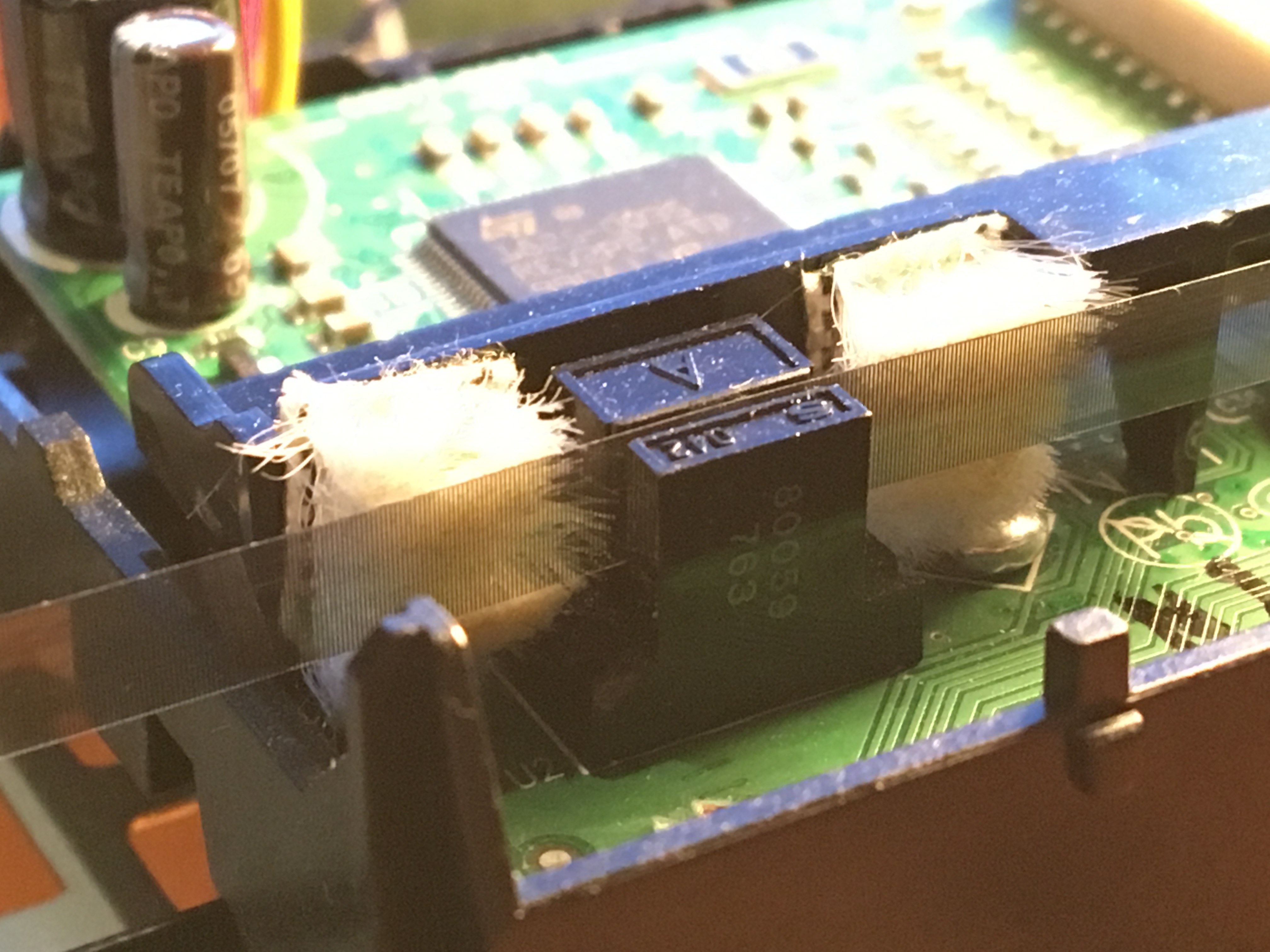
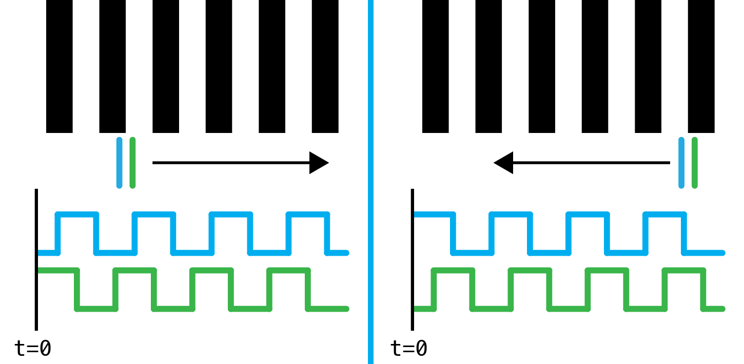
This strip passes through an optical encoder, causing the light inside the encoder to be periodically interrupted. There are usually two photodetectors inside the encoder -- a single emitter/detector pair would allow for sending of speed, but not direction, as moving the carriage in either direction would produce an identical output on the interrupter (a square wave). If two photodetectors are used, then one emitter/detector pair is "interrupted" in sequence, one before the other. The output is two square waves, one which lags or leads in phase by 90 degrees from the other, depending on the direction that the strip is traveling through the encoder. Here's an image which describes the effect.
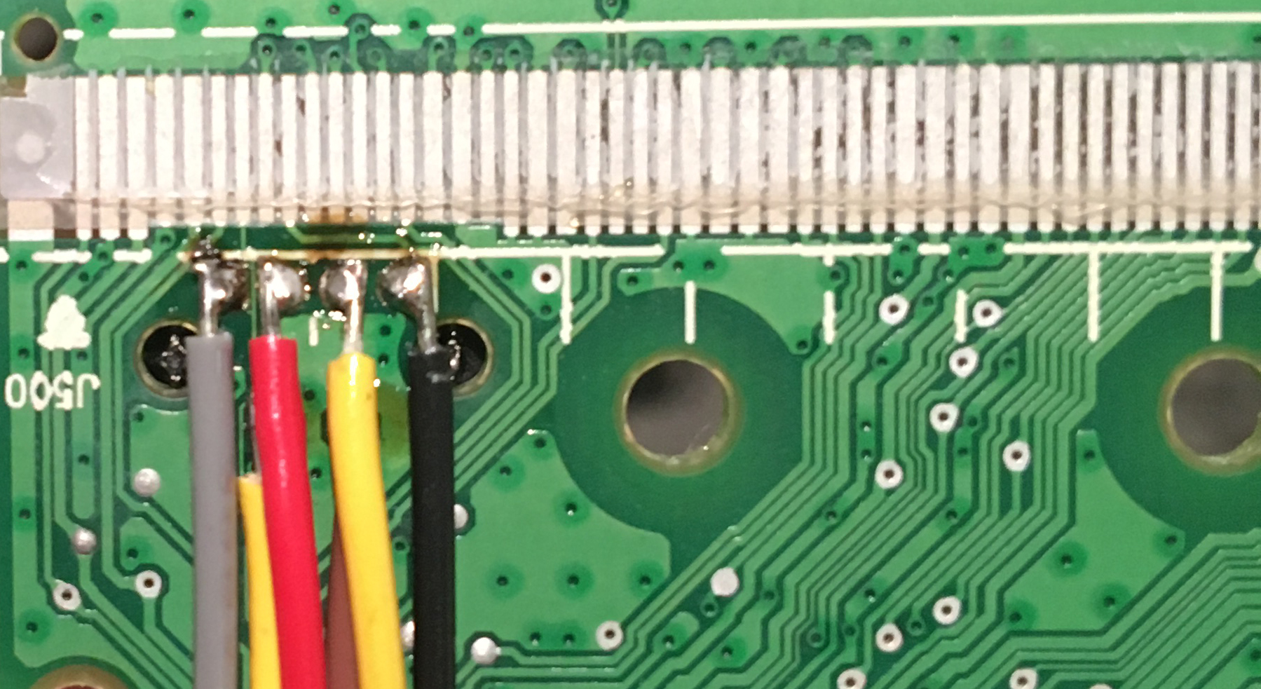
I didn't have much luck finding a datasheet by searching the various numbers that were on the exterior of the package, so I'm assuming it was a part that was custom manufactured for HP printers. Instead, I soldered wires onto every pin of the encoder itself to inspect its operation. I kept all of the electronic guts of the printer, which I managed to figure out how to reconnect. This let me turn the printer on and manually move the carriage to inspect the output of the encoder. I got lucky that the printer turns the encoder on constantly, and not just during printing.
Here's a video I took showing the state of the different encoder pins while it is in motion.
From this, I was able to determine which pins were the output of the encoder, and which pins powered the encoder. The easiest to figure out were the ground pin and the two signal pins. A little more confusing were two pins that were sitting at about 3.3V and one pin that was sitting at about 1.9V. So, I took a guess that there were two infrared LEDs inside the encoder arranged in a common cathode configuration. Infrared LEDs have a low forward voltage (forward voltage and wavelength are inversely related) compared to visible LEDs (a red led has a typical forward voltage of about 2V), which explains the approximate 1.4V drop between the pins.
To power it myself, I needed to know the rated forward current of the LEDs inside the package. I could have cut a trace on the PCB and sensed the cathode current using the voltage across a small valued resistor. Instead, I started with a high valued current limiting resistor, connected the anodes to 3.3V, measured the voltage on the cathode and adjusted the resistor value until I saw about 1.9V on the cathode.
motor control
This was relatively straightforward. I happened to have a Toshiba TB6612FNG breakout board from Pololu handy, which is what I used. The IC is a dual H-Bridge driver. It accepts a PWM signal, so by changing the duty cycle you change the average voltage that is delivered to the motor. The input pins control the polarity that the motor is driven with. Before I wrote any more code, I couldn't resist the urge to hook up some buttons to just turn the motor on in either direction. Here's the result of that.
interfacing
The LPC1768 on the mbed has edge triggered interrupts which I used to detect a rising or falling edge on each output of the encoder. It also has a single quadrature encoder peripheral, but its dedicated pins are not exposed on the mbed, and I am planning on driving two of these carriages for a later project, so I needed to create a solution in software. I used the mbed "standard library" which has classes which perform most of the peripheral configuration. I makes me feel a little too abstracted for an embedded environment, but it's nice to not have to worry about a lot of the hardware details for once.
I created a relatively simple C++ class that represents a "print head" which keeps track of the current position on the encoding strip in "ticks" (initializes to zero), and a current "goal" position which it tries to hold. In what could potentially be called bad design, the class implements a PID control loop internally. The carriage can be moved by changing the goal value.
#include "mbed.h"

class PrintHead {
public:

    // positive is to the right
    // negative is to the left
    int count;
    int goal;
    int last_error;
    float error_integral, output, iterm, dterm;
    float dt;
    float ki, kp, kd;

    PrintHead(PinName left_motor_pin,
              PinName right_motor_pin,
              PinName motor_pwm_pin,
              PinName left_encoder_pin,
              PinName right_encoder_pin) :
              _left_motor(left_motor_pin),
              _right_motor(right_motor_pin),
              _motor_speed(motor_pwm_pin),
              _left_encoder(left_encoder_pin),
              _right_encoder(right_encoder_pin) {

        // change the motor pwm speed for smooth motor operation
        // if the pwm frequency is too low the motor jerks the
        // print head along the track as the PWM switches on and off
        _motor_speed.period(0.00001);
        _motor_speed = 0;

        _left_encoder.rise(this, &PrintHead::left_encoder_rising);
        _left_encoder.fall(this, &PrintHead::left_encoder_falling);
        _right_encoder.rise(this, &PrintHead::right_encoder_rising);
        _right_encoder.fall(this, &PrintHead::right_encoder_falling);

        dt = 0.001;
        _update_motor_ticker.attach_us(this, &PrintHead::update_motor, 1000);

        count = 0;
        goal = 0;
        error_integral = 0;
        kp = kd = ki = 0;
    }

    void left_encoder_rising() {
        if(_right_encoder) count--;
        else count++;
    }

    void left_encoder_falling() {
        if(_right_encoder) count++;
        else count--;
    }

    void right_encoder_rising() {
        if(_left_encoder) count++;
        else count--;
    }

    void right_encoder_falling() {
        if(_left_encoder) count--;
        else count++;
    }

    void update_motor() {
        _left_motor = 0;
        _right_motor = 0;

        int error = goal - count;

        error_integral += error * dt;
        iterm = ki * error_integral;
        dterm = kd * ((error - last_error) / dt);

        output = ((kp * error) + iterm + dterm);

        if(abs(output) > 1) _motor_speed = 1;
        else _motor_speed = abs(output);

        _left_motor = (output < 0);
        _right_motor = (output > 0);

        last_error = error;
    }

private:
    DigitalOut _left_motor;
    DigitalOut _right_motor;
    PwmOut _motor_speed;
    InterruptIn _left_encoder;
    InterruptIn _right_encoder;
    Ticker _update_motor_ticker;
};
I change the PWM frequency of the PWM output in the constructor. I found that the default PWM period is large enough to jerk the carriage as it's moving. The next few lines sets up methods to execute on the rising and falling edge of each encoder output. A "ticker" (really just a timer) is then setup to call the PID control loop method periodically (every 1ms).
The four interrupt methods increment or decrement the current location of the carriage depending on the state of the other encoder output. This logic can be derived by consulting the diagram that was shown earlier.
The update_motor method implements the most basic of PID control loops. I'm controlling on position, which means I have no native control on velocity, acceleration, or jerk. However, those can be metered by implementing higher level control -- controlling how often the position goal is adjusted. The last lines of the method set the motor direction. There is no "left" or "right" motor, just two pins that control if the motor moves the carriage left or right.
buttons
For a grade on the project, I just used two buttons were to move the carriage to the left or right by a set number of ticks.
#include "mbed.h"
#include "DebounceIn.h"
#include "PrintHead.h"

DebounceIn left_pb(p20);
DebounceIn right_pb(p19);

PrintHead head(p21, p22, p23, p24, p25);
Serial pc(USBTX, USBRX);

bool previous_left_pb;
bool previous_right_pb;

int main() {
    left_pb.mode(PullUp);
    right_pb.mode(PullUp);
    pc.baud(57600);

    head.kp = 0.08;
    head.ki = 0.0005;
    head.kd = 0;

    while(1) {
        pc.printf("$%d %d;", head.goal, head.count);
        if(!left_pb && (left_pb != previous_left_pb)) head.goal -= 2000;
        else if(!right_pb && (right_pb != previous_right_pb)) head.goal += 2000;
        wait_us(1);
    }
}
Tuining the PID took a little of work. There was some resonance problems initially.
After a little tuning, it was working reliably. The buttons move the carriage by a set number of "ticks" and after disturbing the position of the carriage it returns to it's commanded position.
having some fun
While buttons were neat, I thought it would be a little more interesting to take an analog input and interpret it as the goal position of the carriage. This way an external signal could be used to drive the carriage to a position. I also output the current position of the carriage as a voltage using the DAC on the mbed. With this input-output system, I could drive the position of the carriage using my function generator, and observe the difference between the instantaneous commanded position and actual position. By driving the system with a sine wave and playing with the input frequency, frequency response of the system can be observed. As the input frequency increases the magnitude of the carriage displacement decreases, as the motor isn't physically capable of moving the carriage back and forth quickly enough to match the input.
The step response could also be observed by setting the input waveform to a square wave. There's little overshoot, which is optimal for my later purpose. Once the square wave frequency increases to a certain point, the position waveform starts to look sinusoidal, meaning the system is effectively a low-pass filter, which is somewhat expected and consistent with the previous results with increasing sine input frequencies.
In addition to being interesting, it was also just pretty fun. The video doesn't show much of the carriage moving, as it's hard to show both my scope display and the assembly, but you can hear the sounds it makes change with the scope display