10/28/2016
vu meter clock | redesign
I just finished building a second version of the sheet metal enclosure for the VU meter clock.
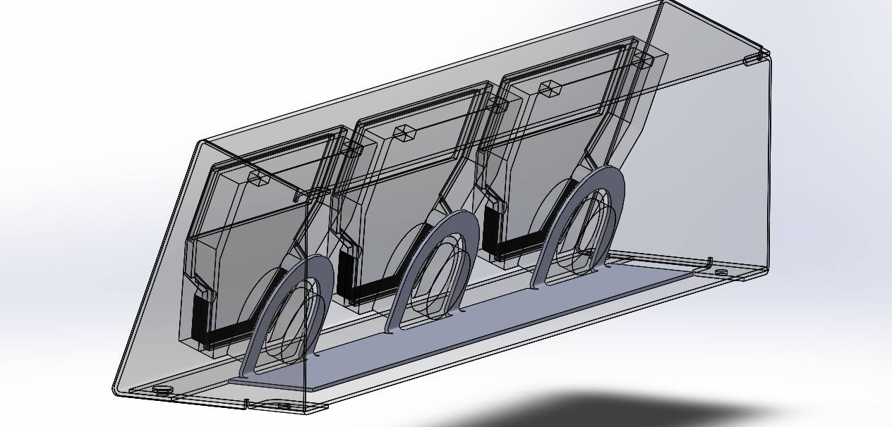
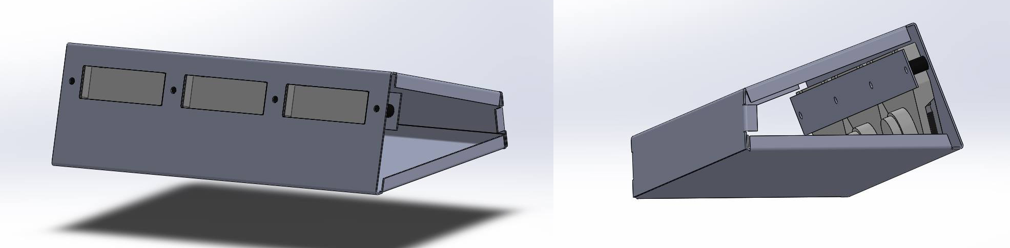
Design wise, I changed it to a five piece design. The main shape is now 3 sides of the clock, with a flat panel covering the bottom. The side pieces now are also flanged, reducing the number of bends in the main shape piece.
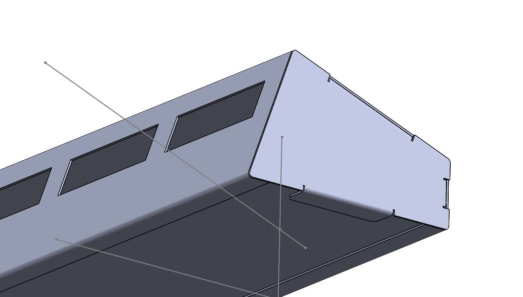
I also redesigned the clamp so that it wraps around the bottom of the meters instead of covering the top. This will allow much more backlight through the meters than the previous design. Not shown in the picture is a slotted cutout in the bottom panel, which will allow for some adjustablity to slide the clamp forwards and backwards if needed. It also helped with assembly.
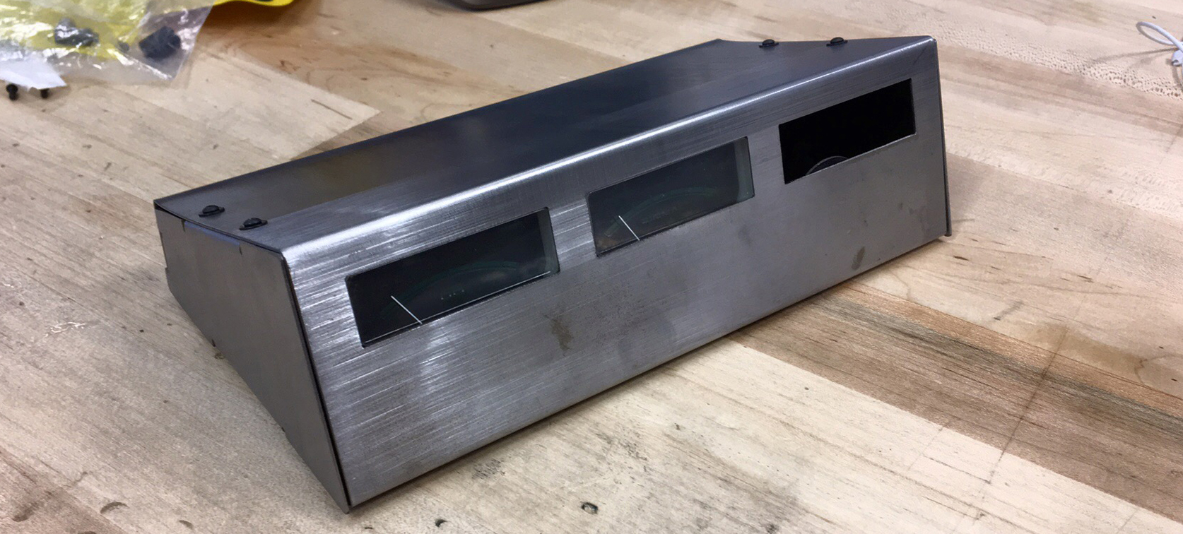
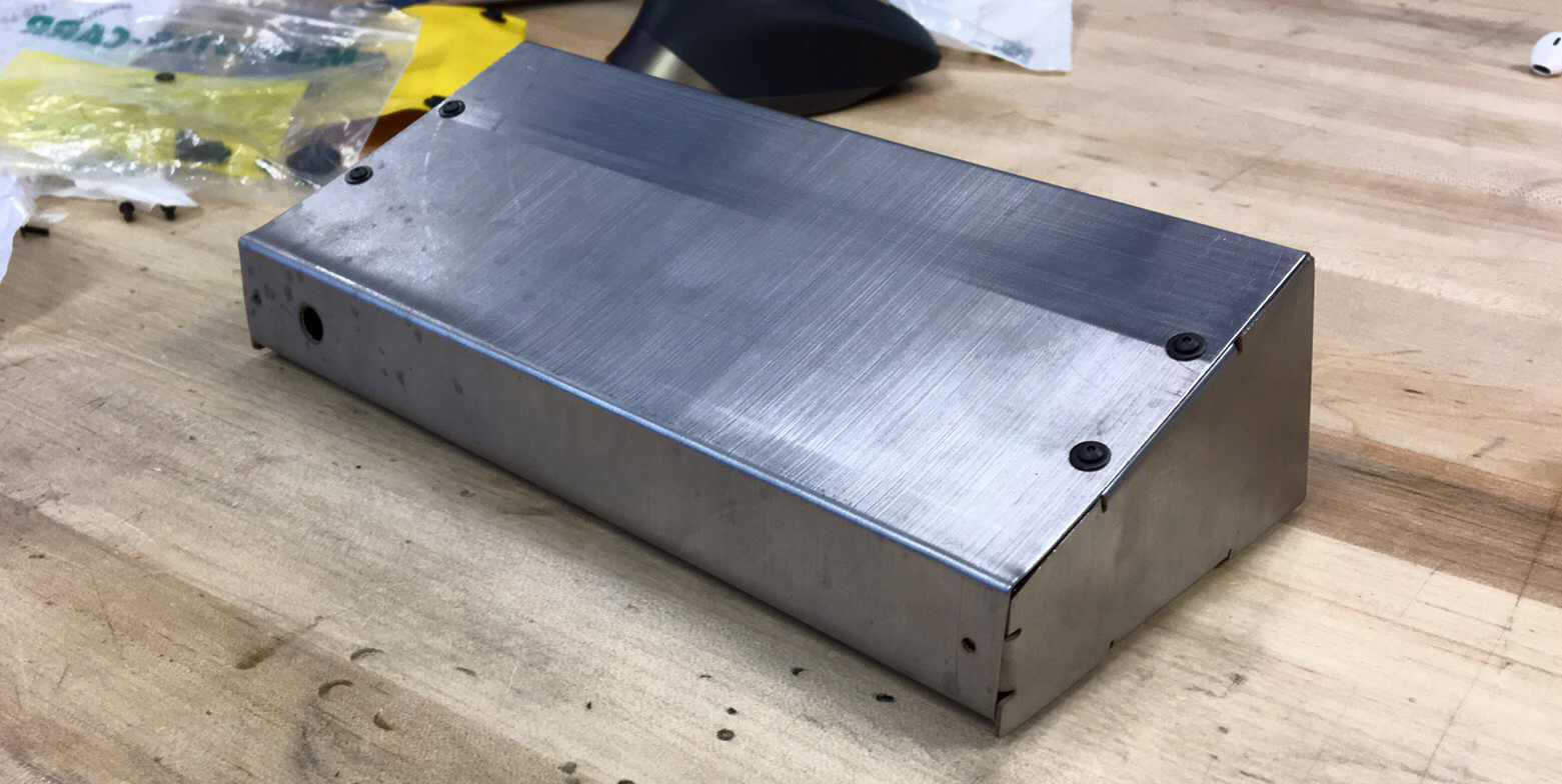
After cutting the pieces out I gave them a good cleaning on the bench grinder and belt sander before installing the press nuts and bending the pieces on the brake. I made one small mistake when reading the bending angle from my plans and made one bend in the main piece too extreme. I managed to bend it back fairly well but I bent the top piece a bit in the process. I think it'll be fine. It's not perfect, but it's acceptable. I like the cleaner look on the front without the holes between the meters. Next step is paint and electronics -- I also need to figure out how to replace the plates inside the meters with time graduations.
10/20/2016
electronic business card | pt. 4
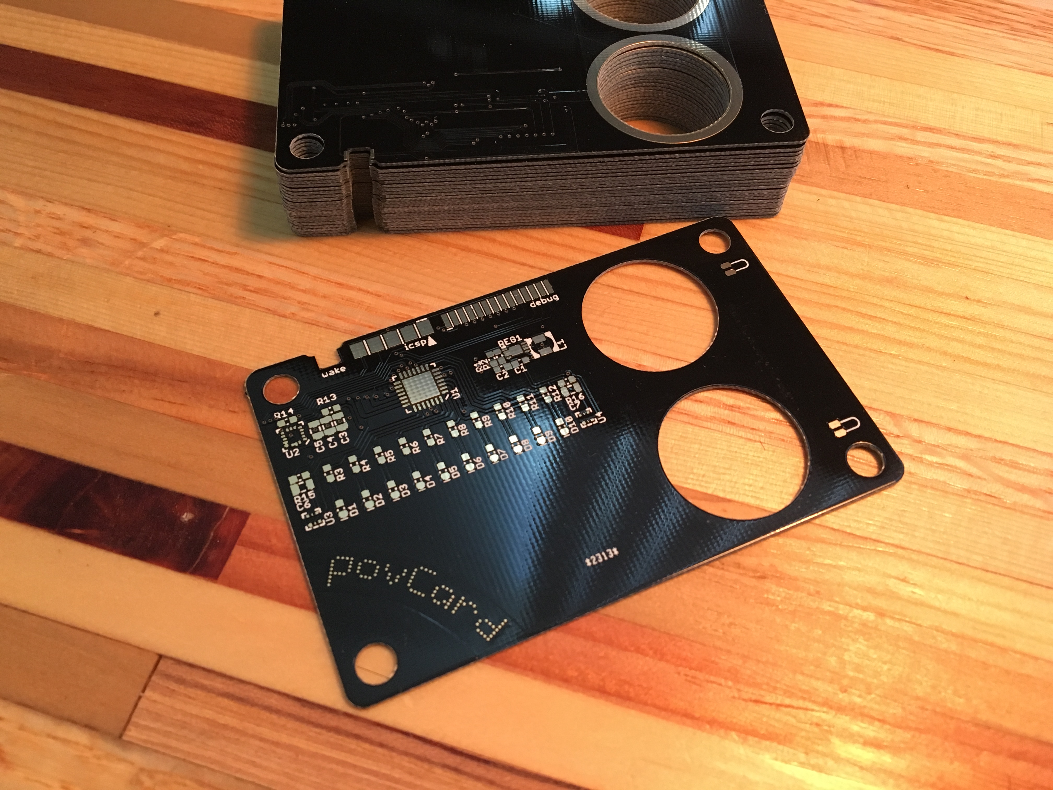
I ordered PCBs last month from two places. Seeedstudio and DirtyPCBs. I've wanted to try these services for a while, and I thought this would be a good test of their capabilities. I placed both orders on the same day, and both orders came to about $75. However, I recieved less boards from DirtyPCBs. Both arrived in the mail on the same day. Although the price on the DirtyPCB boards were slightly higher per board, I would probably order from them next time. The soldermask on the Seeedstudio boards was slighly thinner (and some boards had exposed copper on some traces), and the PCB identification was placed in silkscreen right on the front of the card. The DirtyPCB board had a much more discrete barcode that was laser etched onto the back of the card along the bottom of the board, which was very difficult for me to spot. I hate putting a lot of time into the design of a board for it to be adulturated with some silkscreen from the fabrication house.
Here's all of the boards I got. I couldn't be happier.
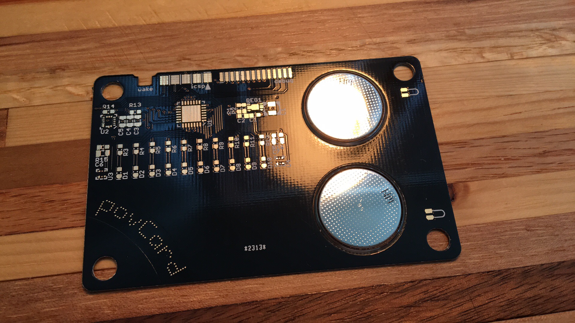
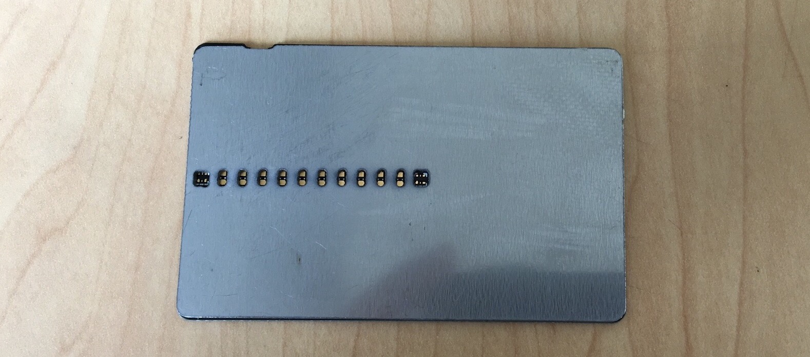
Here's a closeup of how the buttons and batteries fit into the board.
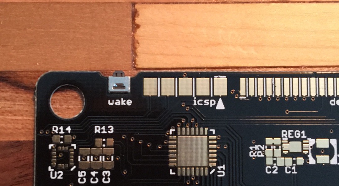
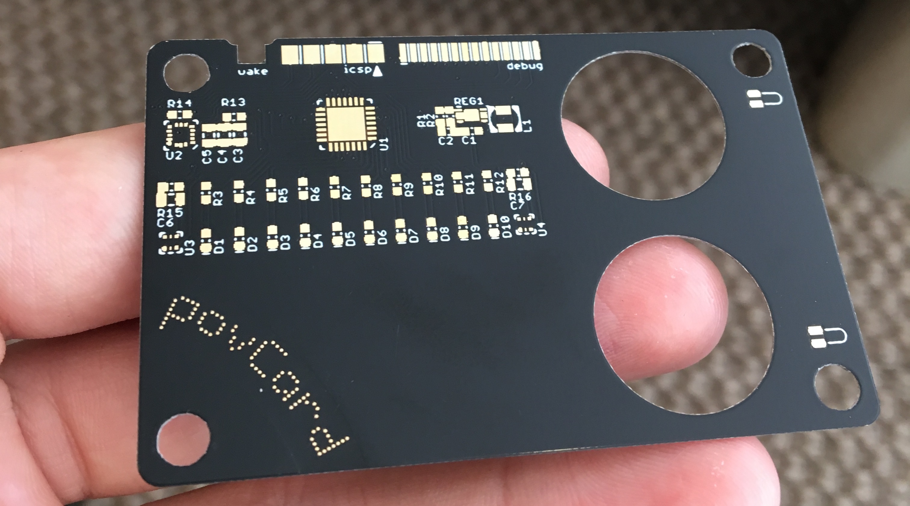
Here's one of the boards from DirtyPCBs, note the lack of the silkscreen identification text on the front.
I ordered a piece of stainless steel from McMaster-Carr and cut the outline and holes out of the steel front piece. -- There was some operator error with the waterjet which caused an accidental crash of the cutting nozzle into the metal. I was instructed incorrectly on what to do when the waterjet software prompted to perform a calibration of the 5-axis nozzle (this allows the machine to cut on surfaces that aren't parallel with the cutting bed). After the calibration was finished, we assumed that the reference "home" position was unchanged and told the machine to perform the cuts. However, the calibration process modifies the machine's reference position. The machine jogs to the home position before starting a cut, which caused the nozzle to move vertically into my piece of metal, leaving it slightly bent, which I didn't notice at first.
When the machine was inspected and re-homed, the cut was made. However, since the piece of metal was slightly bent, the cuts were slightly distored. Which is okay for now. It's a bit of a difficult process to get time on the waterjet, so I'll have to come back another time.
Here's how the steel piece fits over the PCB. Very happy how everything lines up.
The magnets fit perfectly into the holes in the PCB. Here's a video of the PCB snapping onto the steel piece.
I've ordered a very small endmill to do all of the pockets in the steel piece, but since this piece was already not perfect I thought I'd try and see what I could do with a larger endmill. I was very curious if I was going to be able to mill into the thin piece of metal as far as I needed to. I took a series of cuts, cutting deeper into the material each time. I was getting very excited as the DRO was reading that I had cut about 40 thou deep into my 48 thou thick piece of metal. I took the part out of the mill and my excitement was ruined very quickly as I turned the piece of metal over to find a "bubble" of metal sticking up above the rear surface.
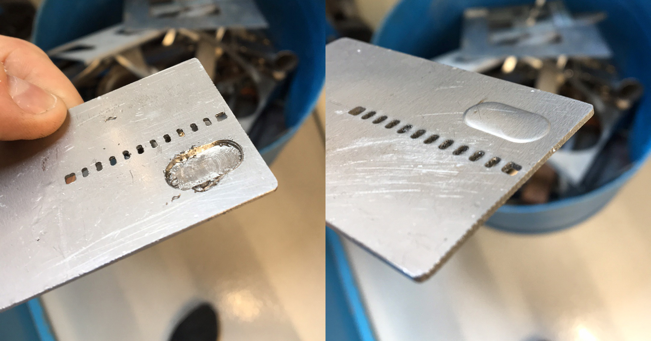
It's pretty clear that as the wall thickness became smaller the rear wall was bent out of the way of the endmill instead of being cut by the endmill. I'm not sure if this can be solved using a sharper and smaller endmill (the ones that are around the shop are fairly abused by students). I asked the shop technicians for some advice and one of them reccomended creating a jig that I can clamp the card down into. That way the back wall has nowhere to go as it is being cut (instead of how I cut it before, which left the rear surface hanging in midair).
I found a piece of aluminum scrap in the shop, and figured this was a good opportunity to learn how to use a fly cutter.
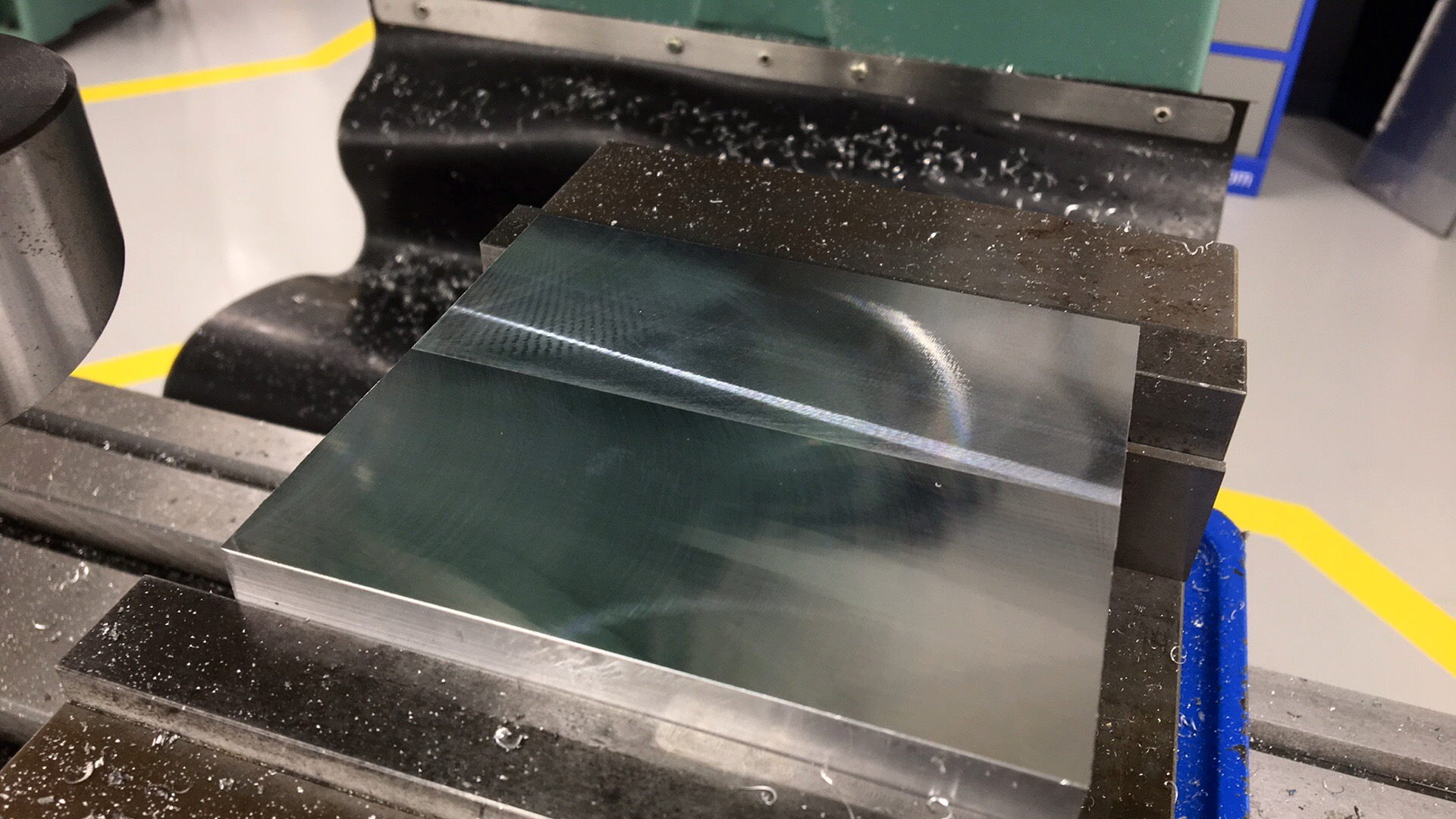
After the surface was flat (which was kind of an unnessassary operation), I cut a pocket into the middle of the block for the piece of steel to sit in (can you see my face?).
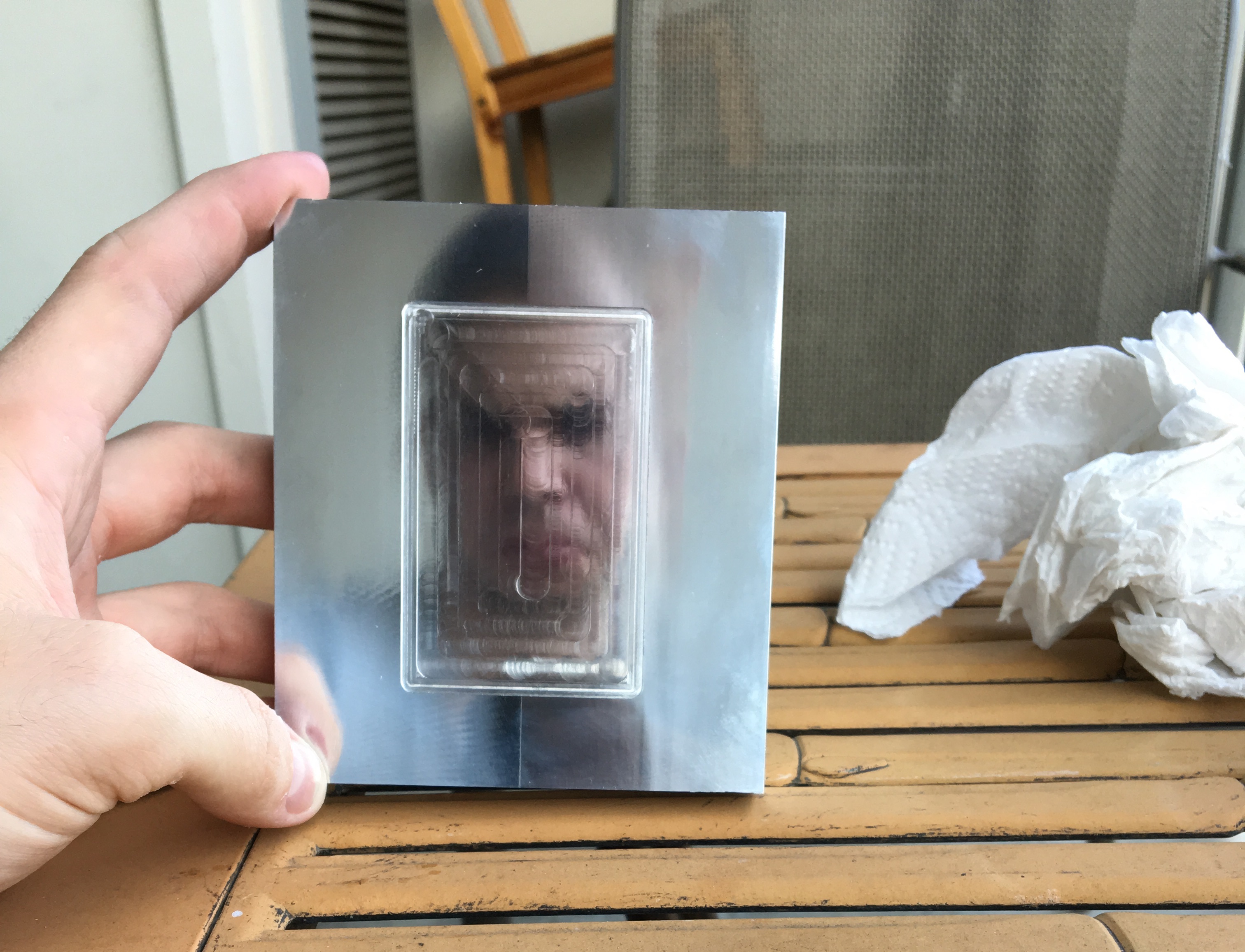
The next steps are to get some new pieces of (unbent) stainless and cut a few more parts out so I have extra. I also need to finish the jig. It needs some holes in it that I can screw some bolts and washers into to clamp down on the steel piece.
10/14/2016
vu meter clock | first prototype
I recently found an old (1980s?) radio/tape player/record player unit sitting in the trash pile behind my apartment. I took it back to my apartment because I thought it would be a treasure trove of electronic and mechanical parts. In taking it apart I scored some motors, pulleys, gears, vintage buttons and bulbs, and a lot of electrical components (though some are usless due to their age). The most exciting components I salvaged were three of these VU meters.
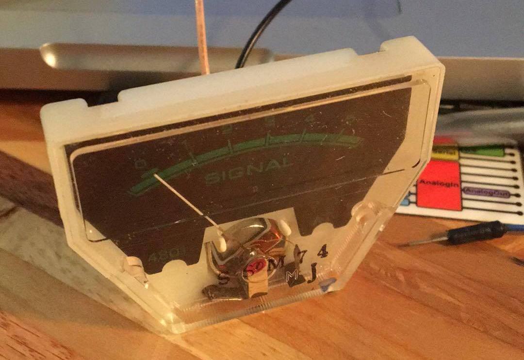
I've been wanting to learn how to use Solidworks' built in sheet metal design tools for a while now as well as learn how to work with sheet metal. I had three of these meters, I figured they'd be perfect to build a clock out of (not that it's a new idea), so I decided to kill two birds with one stone.
I modeled up the meter itself and then just tried various shapes in Solidworks until I was happy with the shape of the enclosure. I settled on this triangular sort of look with the front face sloping backwards a bit, which I thought would look neat as well as make the clock visible when placed on a desk.
I struggled a bit figuring out how I would have all of the bolts go in from the outside and still be able to hold the nut from the inside of the case. I thought for a while about how I would not close up the case while simultaneously preventing me from clamping onto the nuts. I honestly was about to just leave a hole in the bottom until I found these press-in nuts on McMaster-Carr. These are pressed into a hole which makes the teeth on them grab into the surrounding metal. Perfect solution to my problem. I could have also used sheet metal screws, but I was shying away from them.
Here's the water jet cutting out the pieces. I had a bit of a struggle getting the piece of metal to stay flat. I think in the future I'll try and use a sacrificial piece of plywood or MDF to keep the thin metal flat in the bed. If the metal bows up or down while cutting (which can happen easily as the water pressure usually pushes back up as the jet shoots into the water) a slightly distorted pattern is cut.
After the pieces were cut I pressed all of the nuts into the sheet metal. When bending the metal on the brake, I ran into some problems turning the digital representation (which has perfect bends) into a physical one. The main problem was that the main piece bent back onto itself, which made it impossible to make the last bend without the piece running into the brake. Another problem I had was the brake running into the press nuts, which made it hard to get an even bend.
I ended up kind of completing the final bend by hand, just to say I sort of finished it. But the result wasn't pretty.

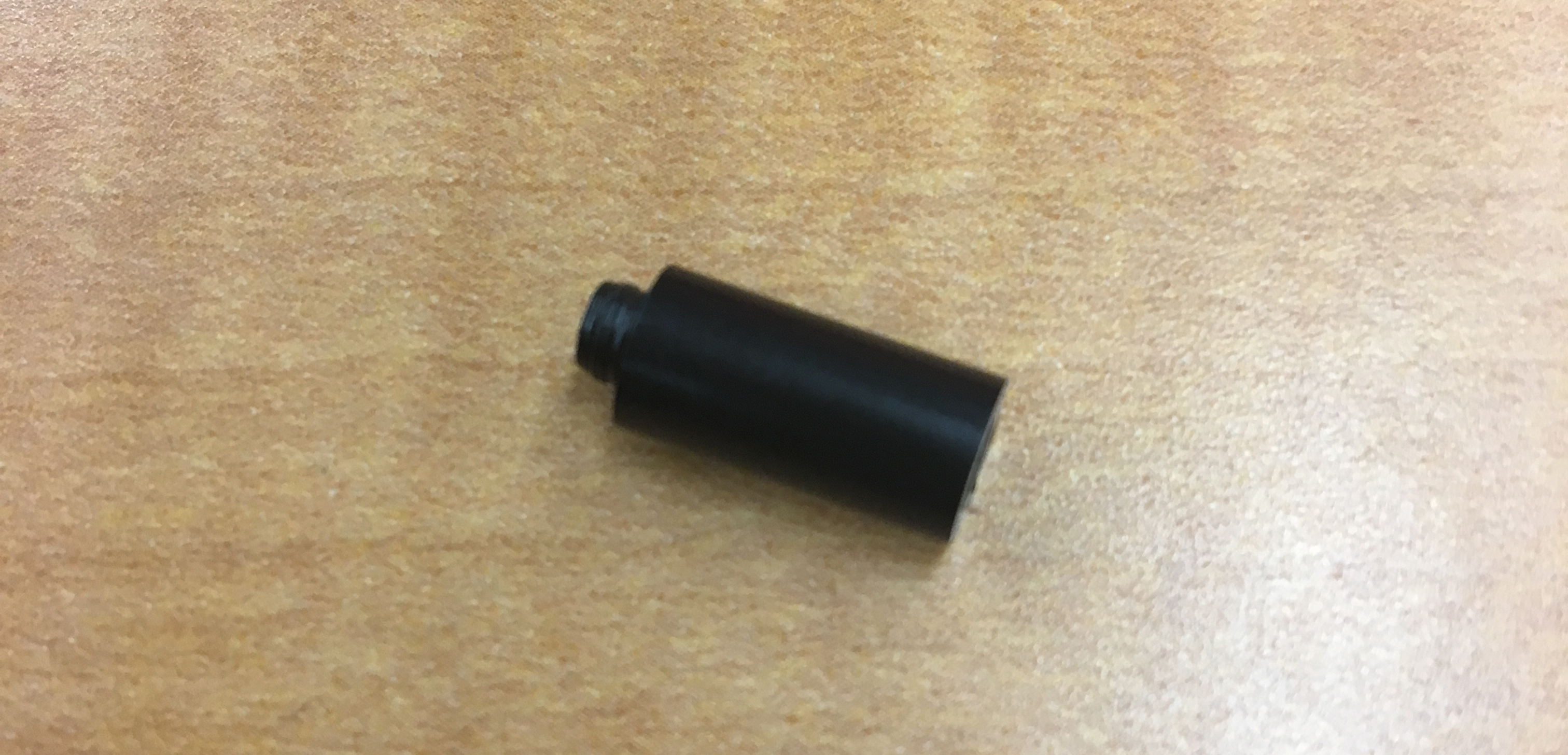
To hold the meters in I was planning on using some spacers but couldn't find any of the right length. They needed to be as deep as the meters so that the bar could go across the back of the meters but still be attached to the front. You can see this in the photos of the 3D model above. I couldn't find any spacers that were the correct length, so I thought I'd try making some on the lathe. I bought some delrin rod and cut some small spacers. They turned out fine, the flange is due to the parting tool. I was going to clean these up but I'm going to redesign the enclosue so that it doesn't require the spacers, so there's no reason to now.
I do want to install some LEDs inside the case to backlight the meters, here's what that might look like.

The last issue I found with this design was that the clamping plate that I desnged to hold the meters in blocks almost all of the backlight from reaching the meter, so I'll have to redesign the clamp so that it grabs at a different location. Not much force is needed, the clear cover on the front of the meter fits pretty snuggly in the holes of the enclosure, so the clamp is just for extra security.