In order to make any of the parts that I need to complete the business card, I needed to be able to use the machine shop that's available to Georgia Tech students to use. I've been an avid consumer of YouTube machining channels for last year or two, so it was awesome to finally get some hands on time with the mill and lathe.
The class was split into two individual three hour sessions that were a week apart. The first class was lathe training and the second class was mill training. We also received some training on the vertical and horizontal band saws. After each class we were given a technical drawing of a part to create on the machine that was covered. To receive certification to use the machine shop, each part had to be made and checked off by an administrator.
Here are the parts we had to make.
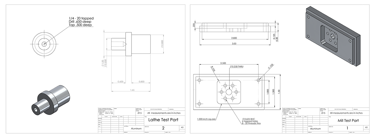
The lathe training focused on manual lathe techniques using the DRO. We learned how find a reference and how to dimension cuts. We also learned how to set the gearing up to do the automatic feed to make a cleaner surface finish. -- The mill training was much more fun. Most of the traditional knee mills in the shop are two-axis CNC controlled with a three-axis digital readout. The interface allows for programming of milling operations. The software keeps track of when the Z axis must be moved, and prompts the operator to move the tool up or down manually before continuing.
We were taught about some of the basic parts of the knee mill: when to use a collet chuck or a drill chuck, how to lock the quill, and how to use the powered draw bar. We were also taught how to use an edge finder, the difference between traditional and climb milling, and the basics of using the ProtoTrak CNC software/DRO installed on the mill. Overall, pretty basic stuff, but enough to make a fair amount of complex parts on the mill.
Here's a pocket being milled into the part I had to make.
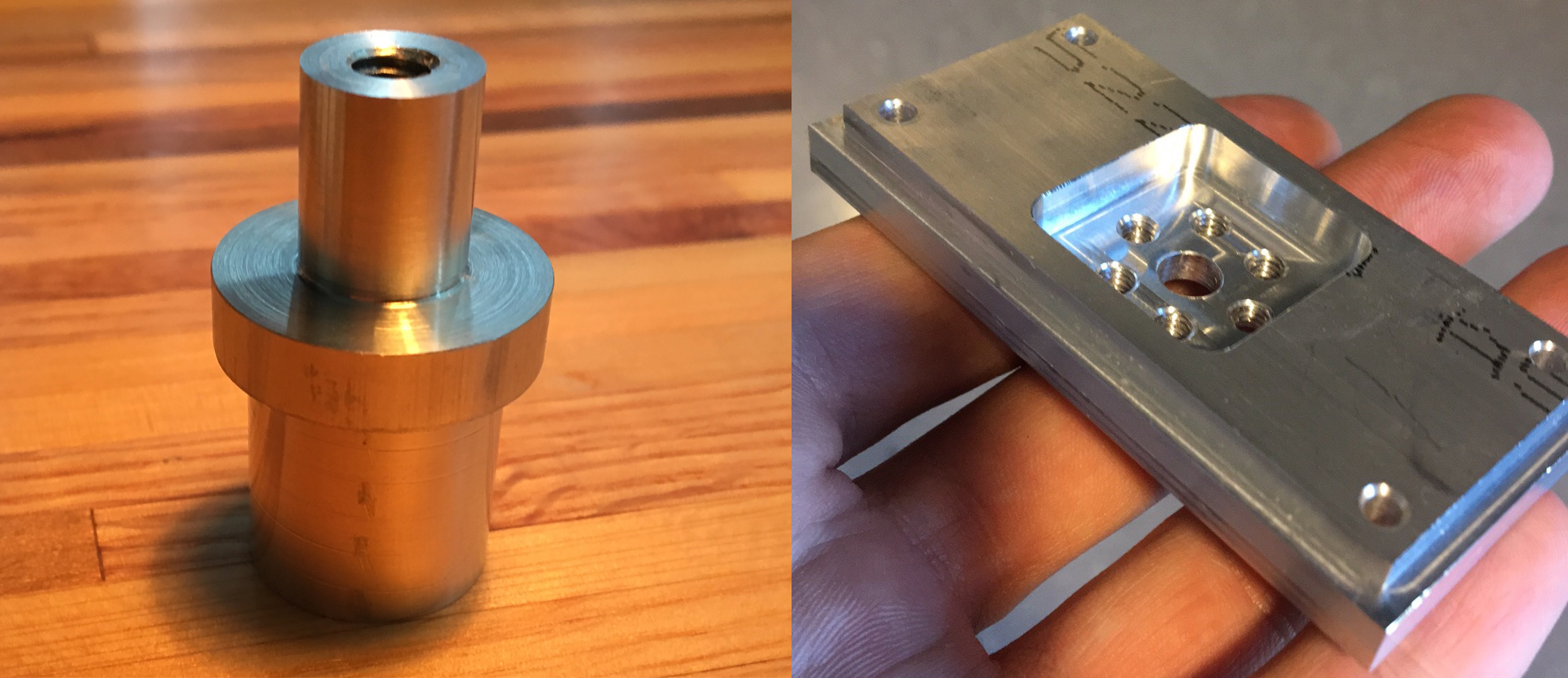
Here are my completed parts.
Although I'd like to get onto milling the business card parts, I did want to get a little more practice. They had some more plans for another project that a lot of people in the machine shop build, which is a little C clamp. It includes multiple parts that have to be machined on the mill and lathe. For some more practice translating drawings into 3D models, I put it into Solidworks.
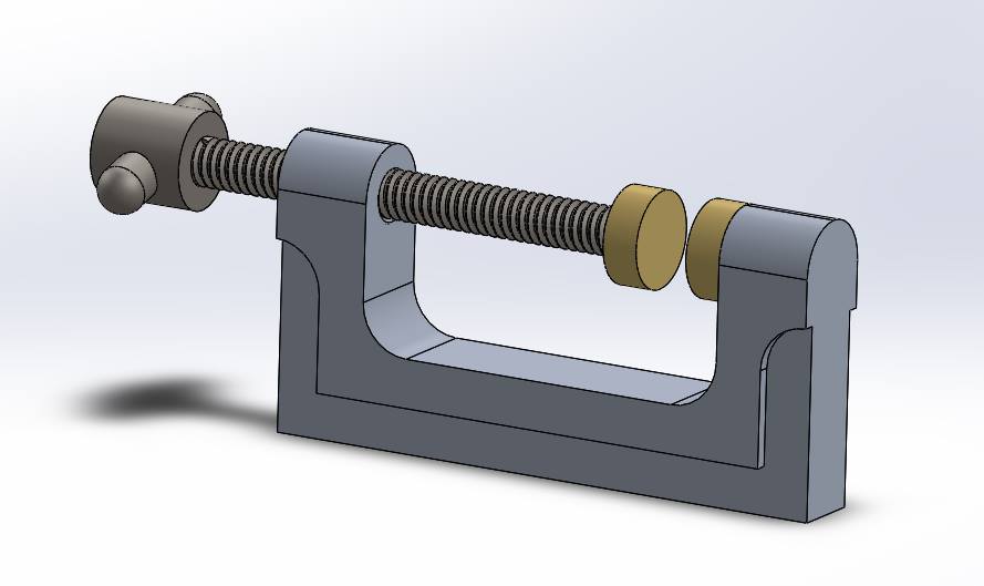
I got pretty far into making the main body of the clamp before realizing I'd like to get going with the business card. So I've stopped working on it for now. Machining the clamp taught me how to think about the ordering of cuts and how to strategize how the part will be clamped.
If anyone is looking for some interesting/educational videos regarding machining, I'd recommend (in no particular order), This Old Tony, Abom79, Clickspring, NYC CNC, Keith Fenner, and Suburban Tool Inc, to name a few.
08/20/2016
replacing kinked oil tubing
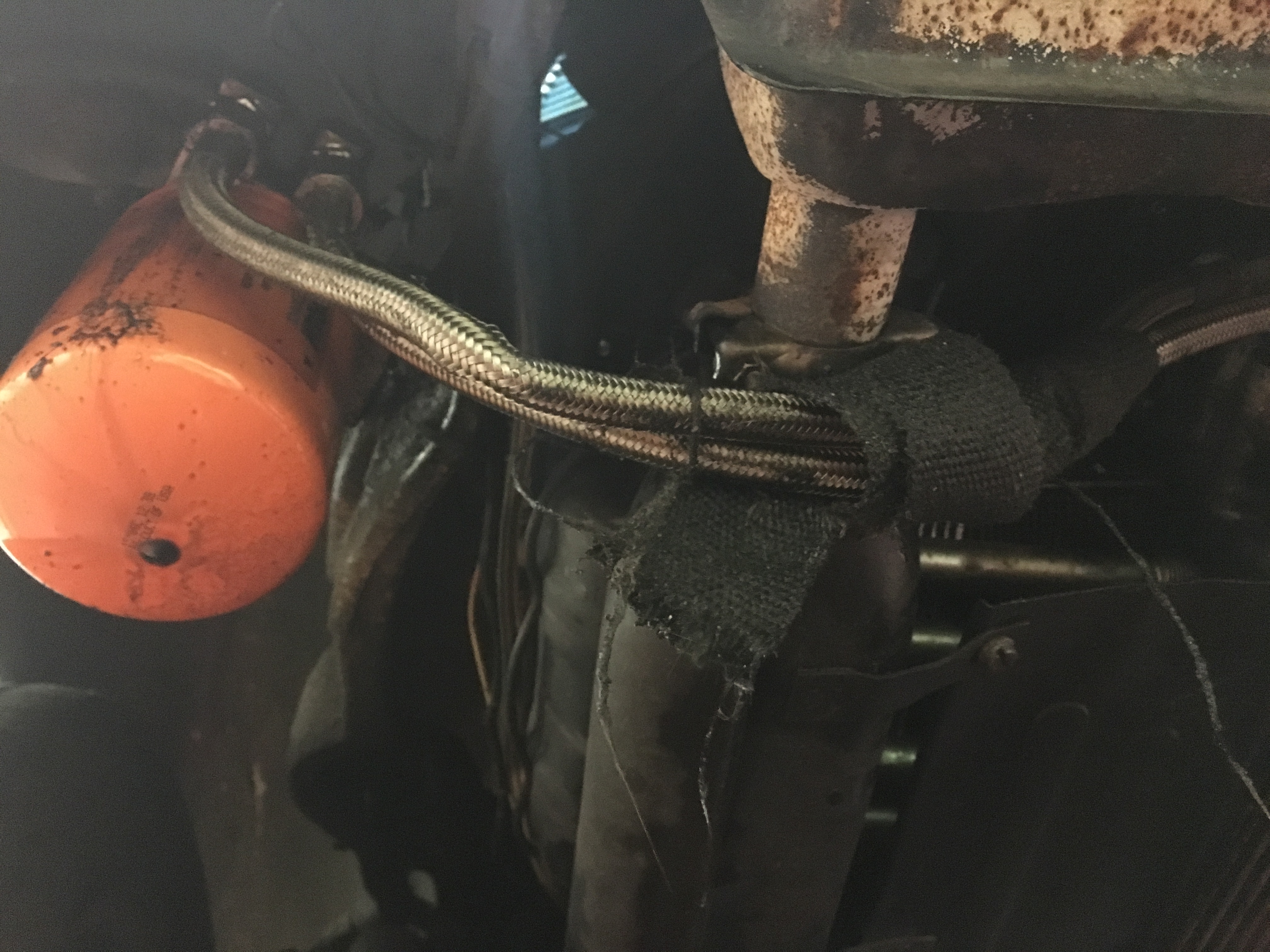
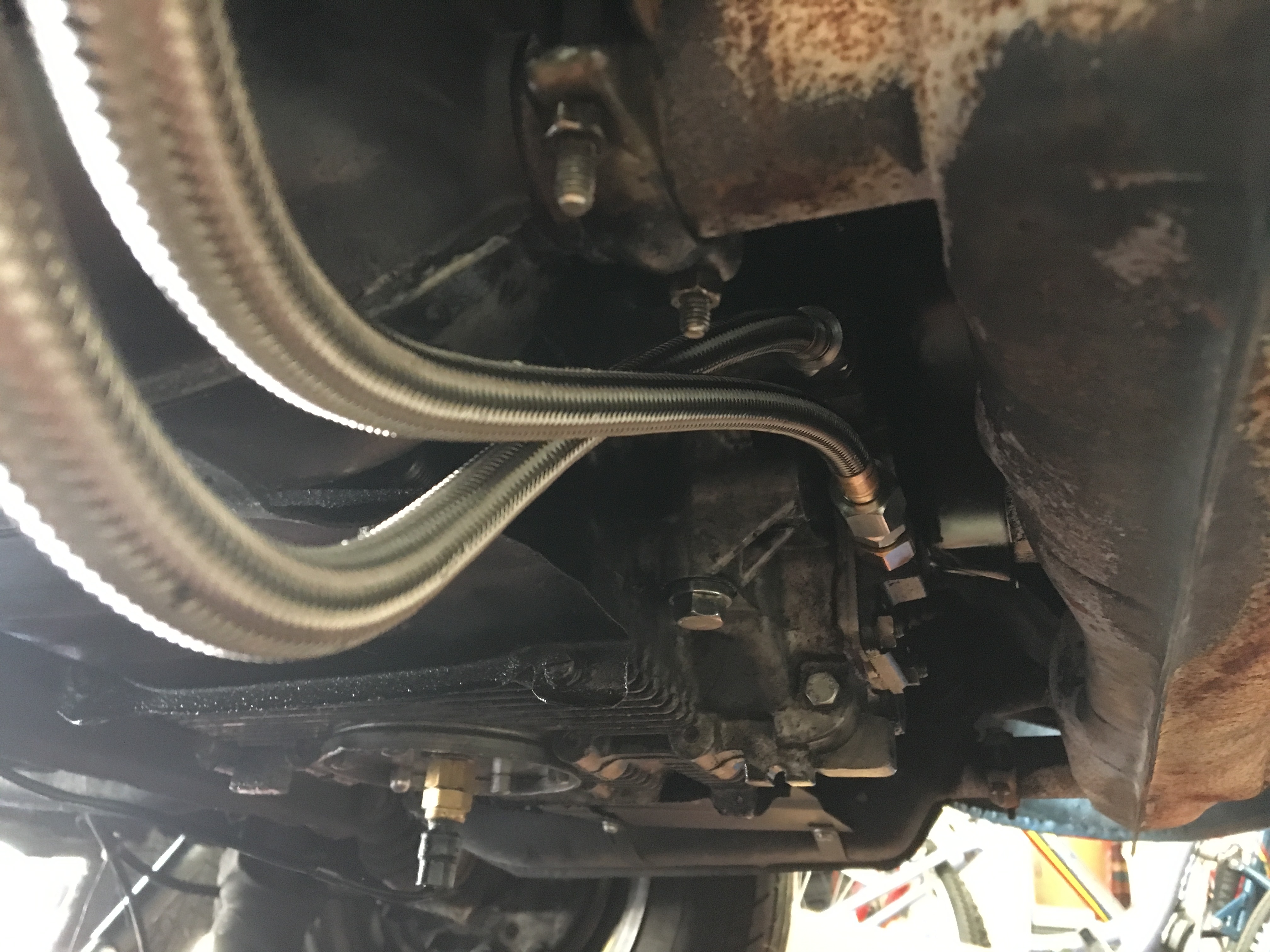
When I installed the remote oil filter mount on my car (discussed in my engine rebuild entry) the hoses I had were a little too short for comfort to reach from the oil pump cover to the filter mount, which brought them a little closer to the exhaust than I would like. I did place some heat insulating exhaust wrap around the hoses, but I have still been worried that the oil is being heated by the exhaust. More seriously, I also placed a mild kink in the hose when trying to tighten both ends onto the fittings, so I've been worried that I've been running with reduced oil flow and pressure for a while.
I ordered some replacement hoses of longer length from Gene Berg Enterprises and just finished installing them. -- Here's what the hoses looked like before replacement. You can see the kink, and the proximity to the exhaust.
I had some trouble with oil leaks from these fittings in the past, so the challenge was to try and get as much oil and old teflon tape off of the fittings before reinstallation. I ended up using my phone as a borescope while using a small curved pick to grab the old teflon tape out from the threads of the male pipe fittings.
After a lot of careful cleaning I reinstalled the hoses. This time I was a lot more attentive to what the hose was doing as I tightened each end. It'd almost be nice if one end was reverse threaded so that the hose would want to tighten itself on both ends instead of kinking. The hose should be allowed to rotate freely, but tightening presses the flared ends of the hose up against the mating surface of the other fitting, preventing the hose from rotating.
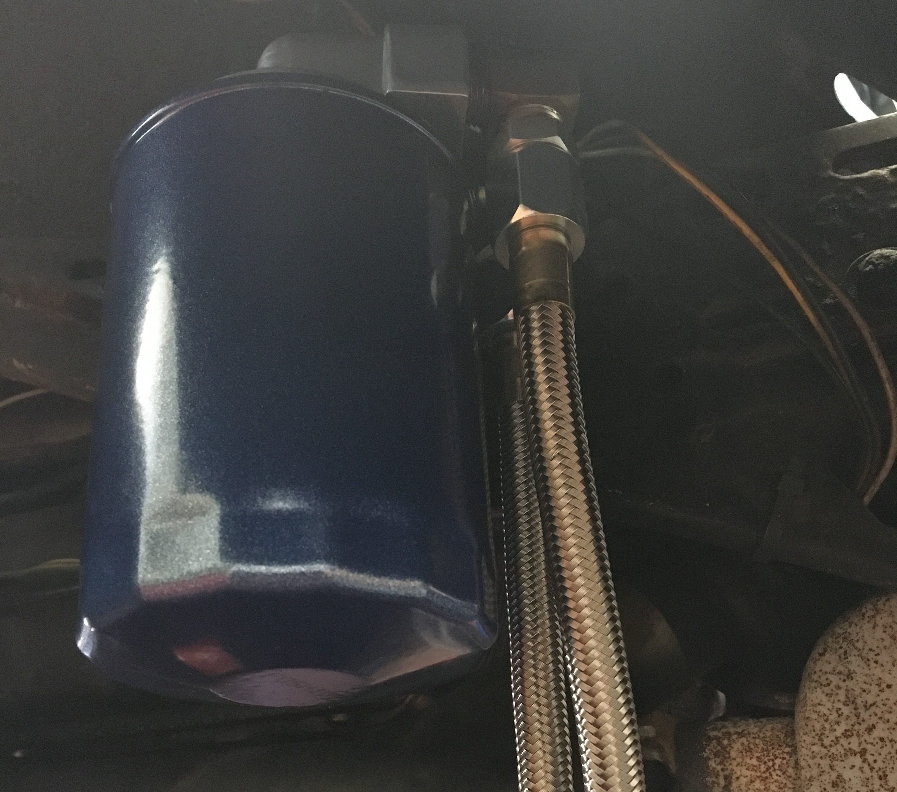
Here's the end result. A lot cleaner than the previous installation, and the hoses are now comfortably below the exhaust. Hopefully the new teflon tape should keep them from leaking. (The oil temperature sensor can be seen in the first photo installed in the oil sump plate)
08/13/2016
custom VW gauge mount
I wired up some SpeedHut Revolution gauges last year with the help of some friends in the local VW community. There wasn't enough time to mount them in the dashboard properly before I left to California, so they've been wired up in the back seat of my car mounted in the cardboard box they came in. While having the gauges makes me feel more confident about the health of my engine, having to peer over the back seat to check my oil temperature and pressure is a little dangerous. I just got back from my internship and have a little time before school is back in full swing, so now was a great time to get them properly installed.
I might cover the sensor installation at a later time. The pressure sensor is on a tee fitting off of where the stock oil pressure "switch" is normally mounted. This allows the new sensor to coexist with the old switch. The tachometer only requires one sense wire off of the primary side of the ignition coil. The oil temperature sensor is in the oil sump plate, and is not actually working well, which I'll need to fix later. The sensor doesn't see a lot of flow over it when sitting in the sump, and the body of the sensor itself is sticking directly in the air stream flowing underneath the car. It takes a long time on the highway for the sensor to read on the gauge, and the reported temperatures drop almost immediately when the car begins moving.
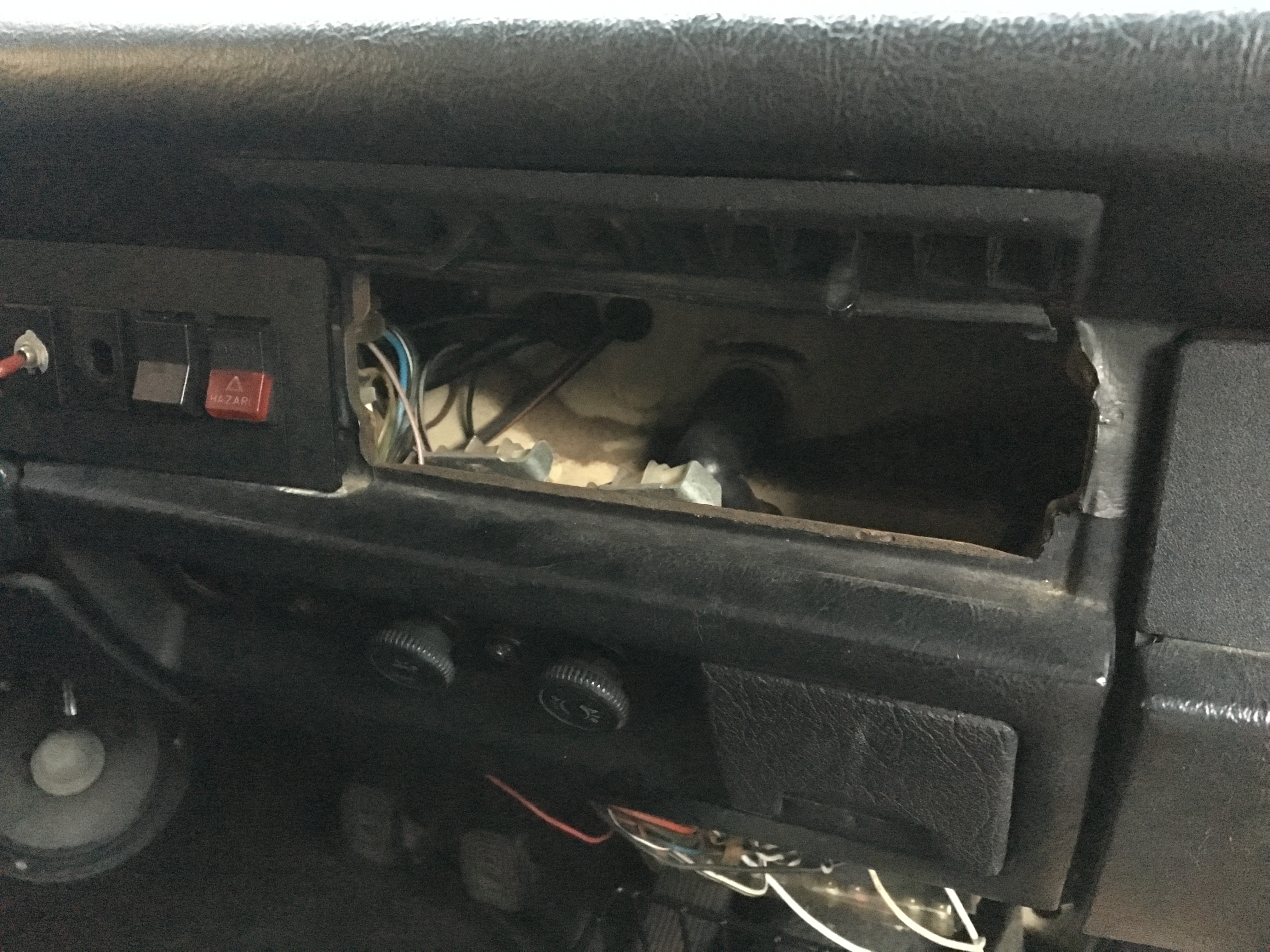
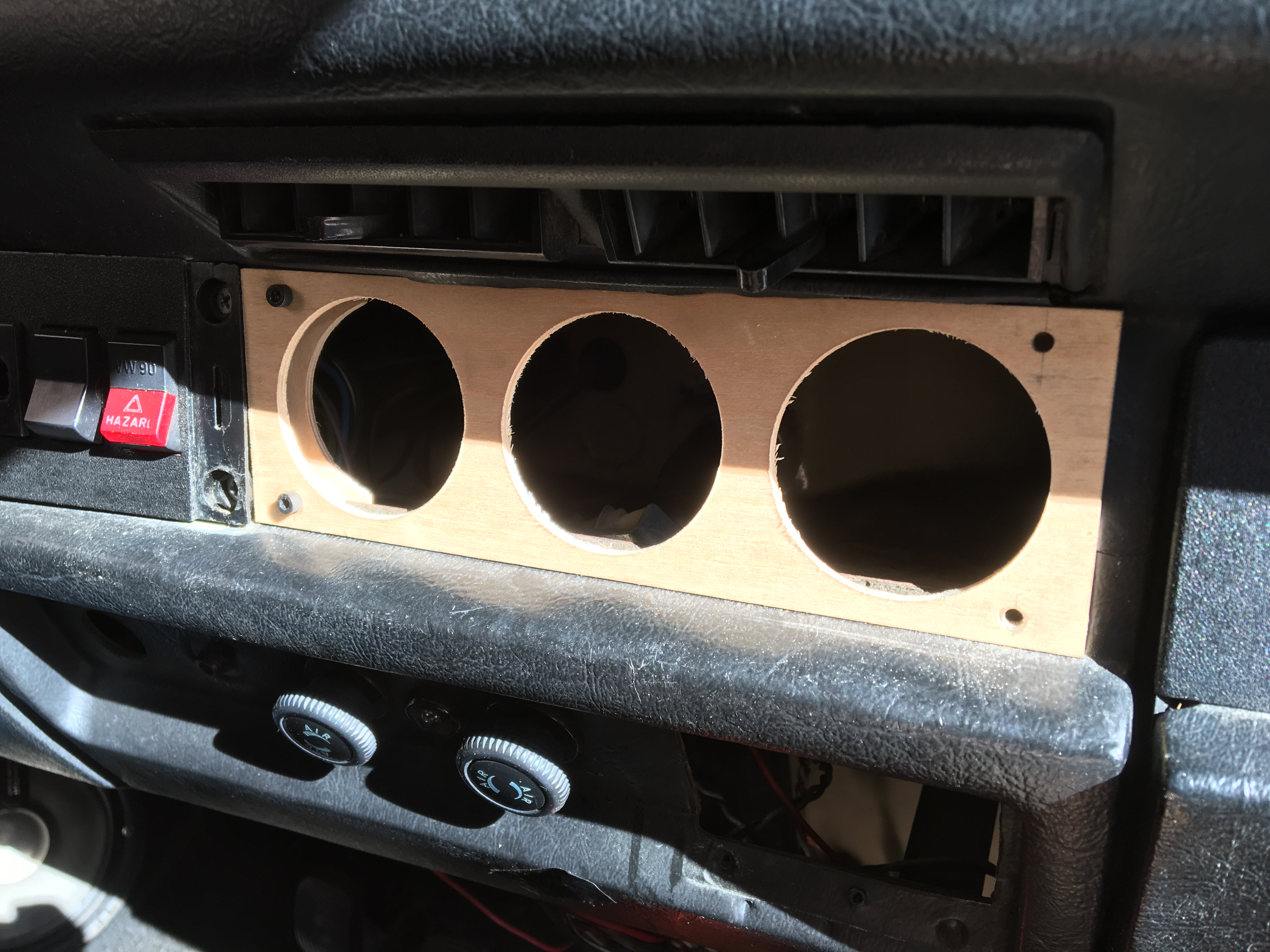
A previous owner had installed some gauges in a dash cover plate. The installation was very sloppy (the gauges aren't level with one another, and don't fit correctly in their mounting holes) and the gauges were nonfunctional when I purchased the car. There isn't enough space to fit three gauges in the same location, and I eventually want to find a replacement dash cover plate that is unadulterated to bring the car back to a stock dashboard look. I don't have the stock radio in my dash and I don't plan on having one anytime soon, so I thought the gauges would be a good way to cover up the gaping hole in the middle of my dashboard.
I had thought about laser cutting a custom piece of acrylic or something, but I really just wanted to get the project done. I had some thin plywood laying around so that's what I used. I measured the hole in the front and cut a rectangle out to size on the table saw. I used a hole saw to cut the holes in the front of the panel.
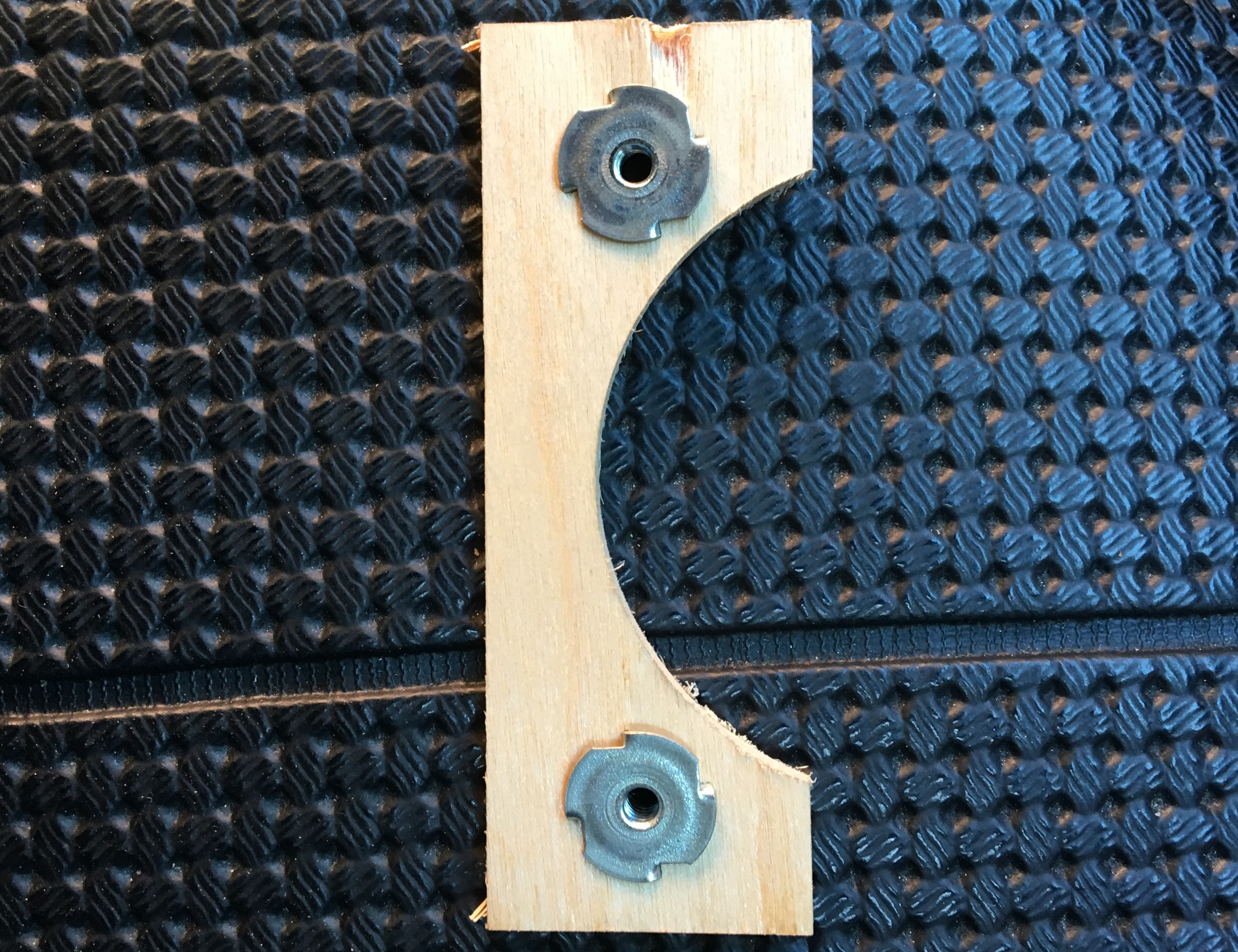
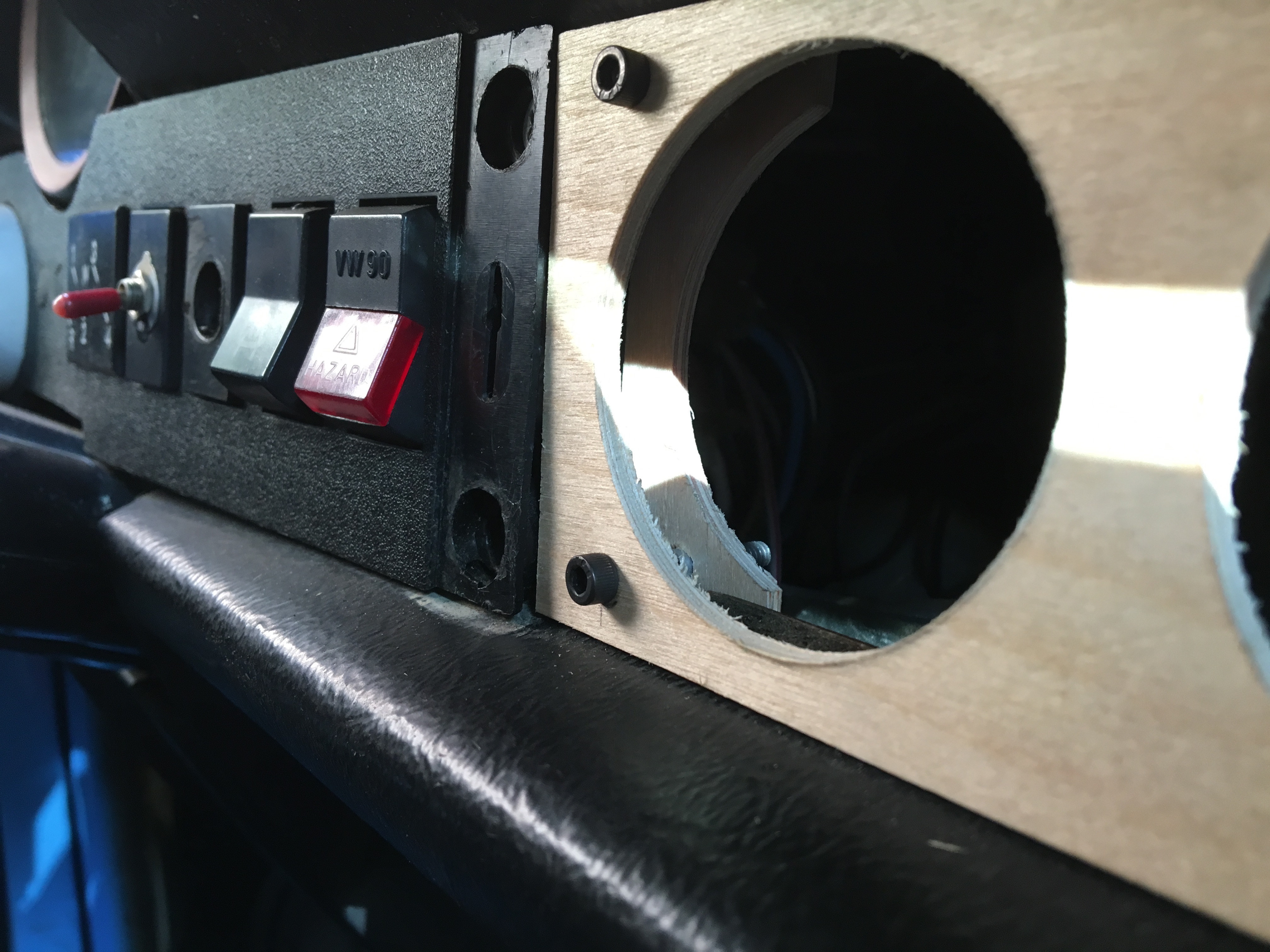
I used two pieces of wood on the other side of the flange in the dashboard to clamp the panel around the flange. I cut a hole the same diameter as the body of the gauge in a square piece of plywood and then cut the square in half. I mounted two press nuts into these two pieces.
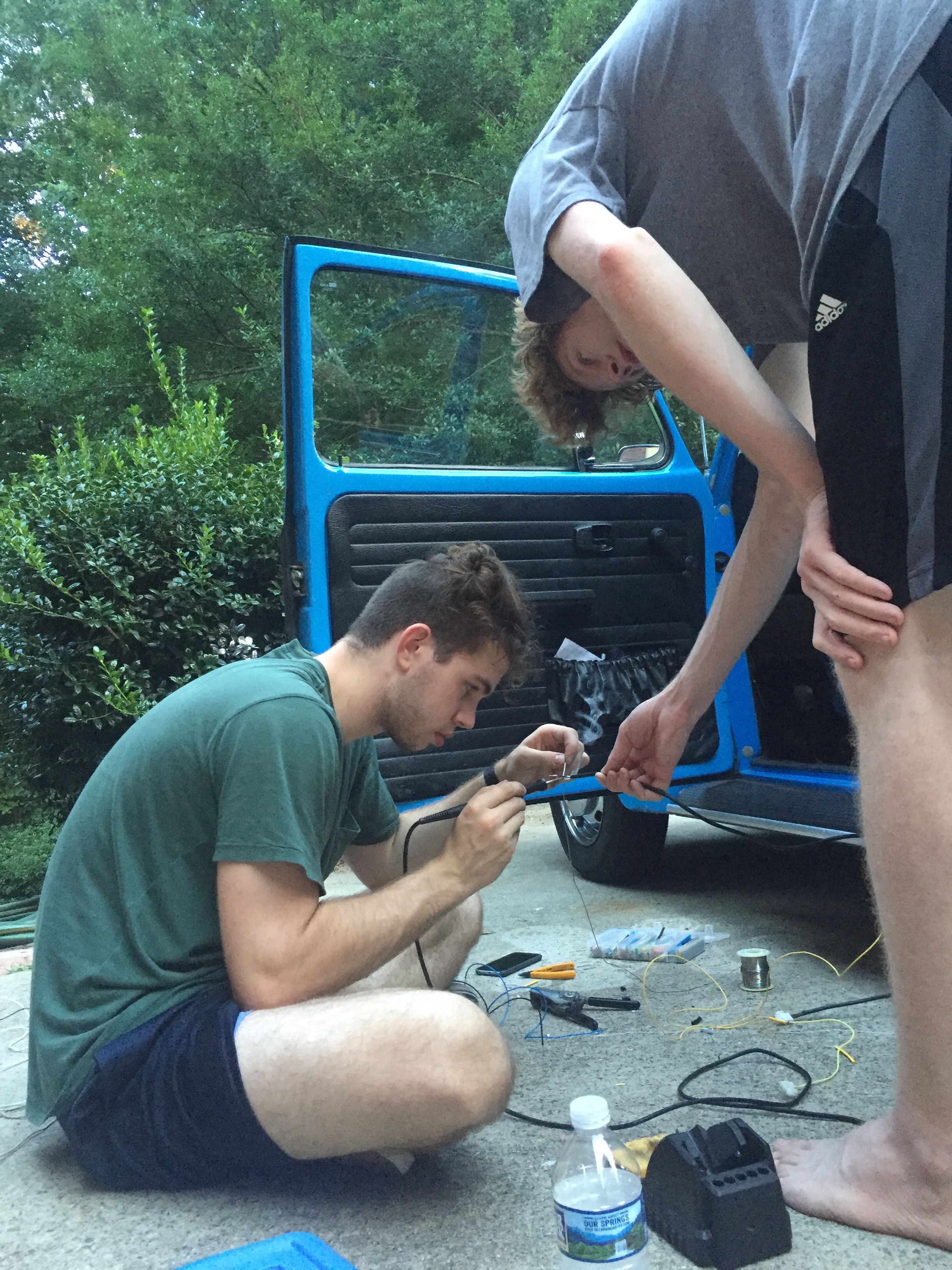
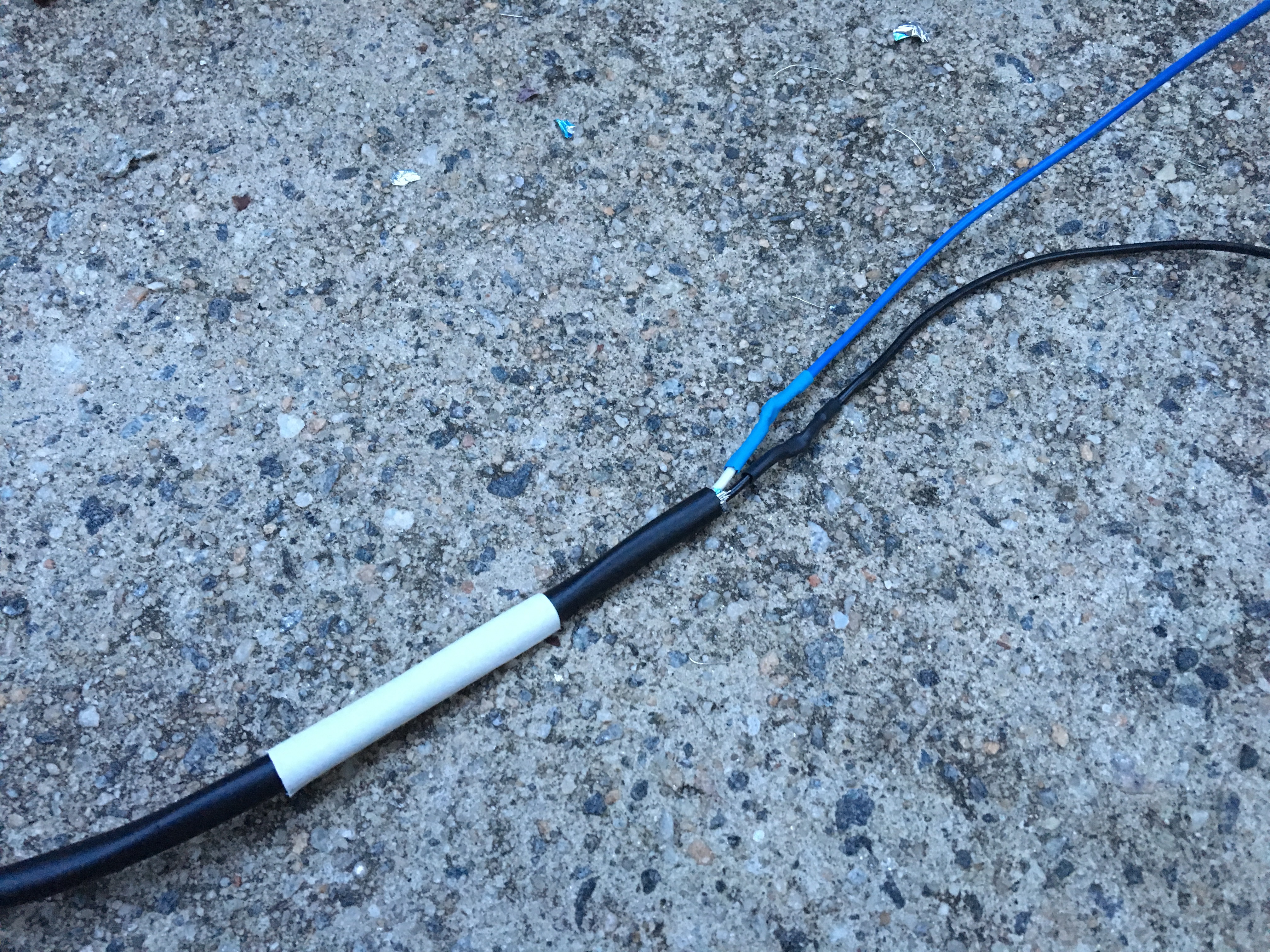
The wire runs that were included in the kit were intended for a front engine car, so the wires typically only have to reach through the firewall from the front of the car to the dashboard. Since the engine is in the back of my car, I had to splice quite a bit of wire into each bundle. I opted to solder the wires instead of using crimp connectors. I also added some heat shrink tubing to the junctions as well. Here's a boring photo. This ended up being quite a bit of work as each wire that needed length added to it had to be soldered twice (I needed to keep the correct connectors on both ends of the cable). My brother helped a lot with holding the wires.
After that was done, the gauges could be installed.
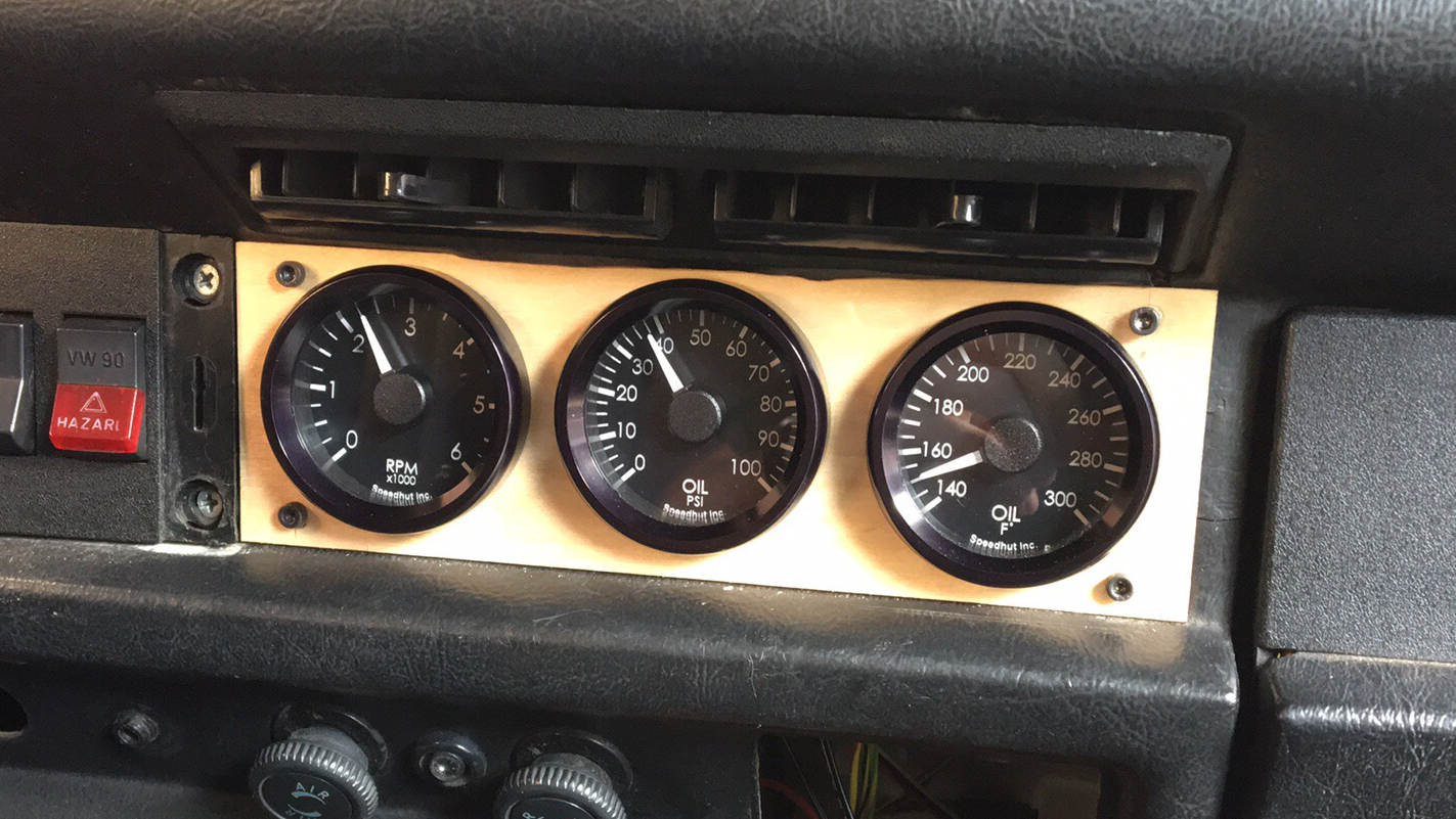
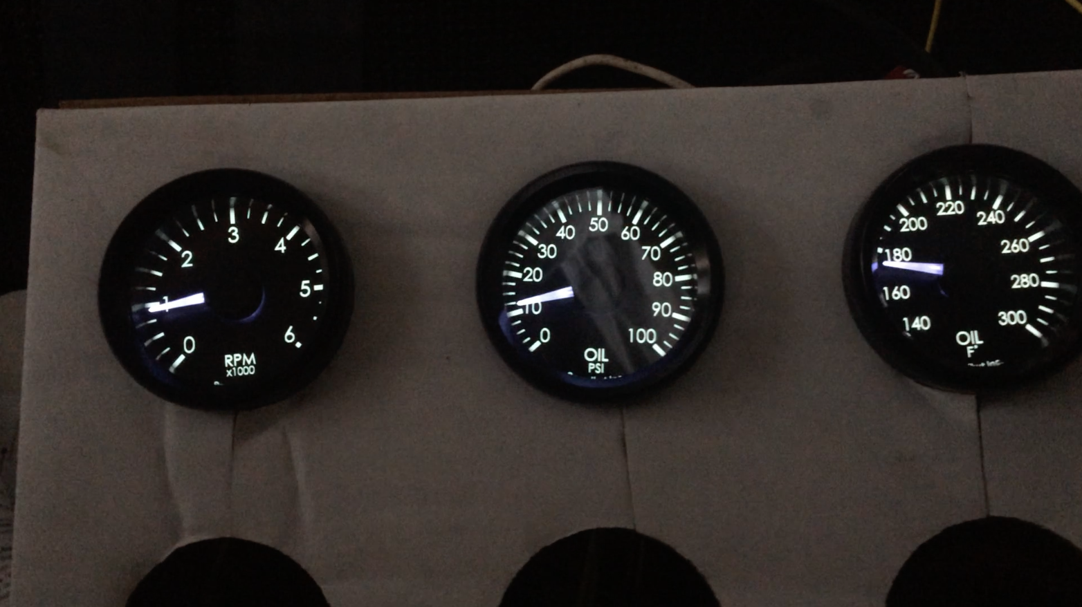
Here are the gauges in action.
Currently, the Speedhut lighting controller has a potentiometer that controls the brightness of the backlights of each gauge. I'd eventually like to wire that up to the car's dimming wheel, so that the stock brightness wheel controls speedometer and "map light" as well as the new gauges.
Overall, I'm super happy with how it looks. I think I might want to paint the panel black, but for now I'm kind of enjoying the wood grain. I probably should add washers under the bolts, but it was huge pain to get the bolts lined up correctly with the press nuts in the clamping pieces, so I'm not super inclined to go through the process again just to add some washers. -- If I were to do it again I'd probably drill an oversized hole in the rear and use a traditional nut instead of a press nut. Using the press nuts meant that the hole pattern in the front and rear pieces had to be almost exactly the same for both bolts to thread in correctly.