I've decided to build an enclosure for my 3D printer, for three reasons: noise containment, temperature control, and vapor containment. Though the printer is quiet, it's not quiet enough to print overnight, which somewhat limits me to shorter and smaller prints. I also want to try printing ABS, which prints better when the enviromet temperature is stable and above room temperature. ABS also emits a strong odor when printed, so I'd like to try and contain that as well.
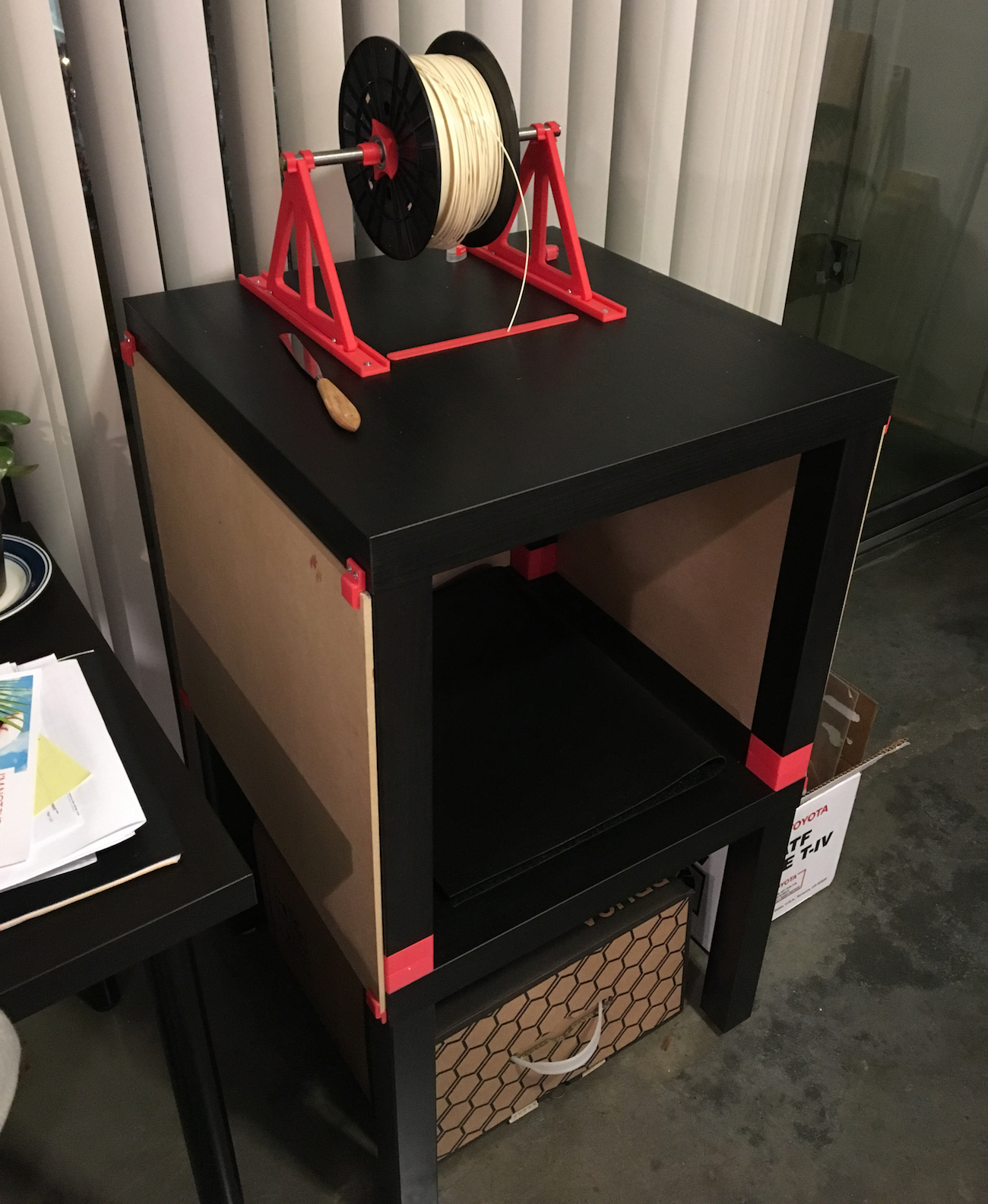
I've seen lots of enclosures built out of the these Ikea LACK side-tables due to their low price. There are some completed enclosures here, here and here, though a search for "ikea lack enclosure" brings up many more results. Though it seemed like a good design at first, if I were starting over I would build the enclosure from scratch using aluminum extrusions or wood.
The concept is similar in all of the designs. One side table is stacked on top of the other. The printer goes the tabletop of the bottom table, and some sort of spool holder mounts to the tabletop of the top table. Some siding is mounted from leg to leg of the top table on three sides, and an access door goes on one side. This forms a box. More features are sometimes added, which I may consider when the enclosure is finished. These include an auxillary exhaust fan to control the temperature inside the enclosure, interior lighting, a master power switch, and an externally mounted display for the printer.
I thought this would be a good time to get even more familiar with Fusion360 and more experienced with my printer, so I decided I'd try and 3D print as many of the parts and design them all inside Fusion360. Trying to print most of the parts was also probably a bad idea, and my inner woodworker died a bit inside during the process, but that's okay, he'll live.
making clearance for the printer
The first step in all of these enclosures is lenghtening the legs in some fashion. The legs on the Ikea tables are just a few inches too short to fit the Prusa i3 under comfortablly. I designed and printed these little "peg-legs" for each leg, which each has a cooresponding socket that mounts to the tabletop of the bottom table.
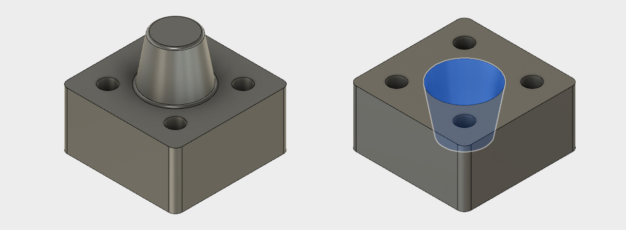
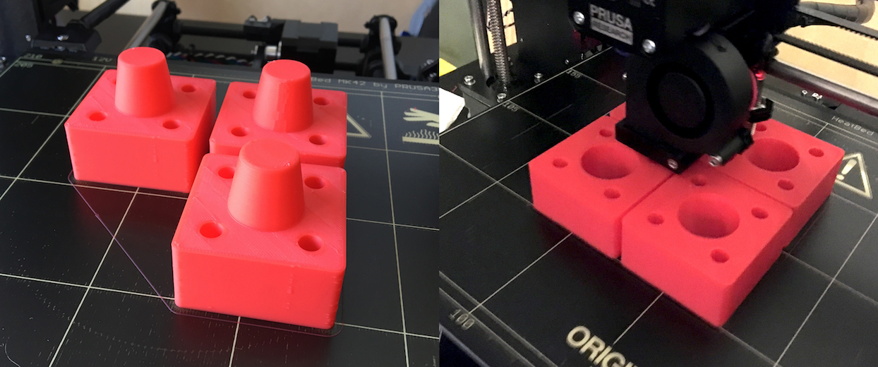
This was my first time printing with a layer height above 200 microns. These were printed at 350 microns, and it was amazing to watch the plastic fly through the extruder. I a group of four (sockets or pegs) printed in about three and a half hours. Pretty incredible.
spool holder design
Since the spool no longer will fit atop the printer, it needs to be mounted on top of the enclosure (or somewhere outside where the printer is). I wanted something that would accept different spool sizes (both inside and outside diameters) and would allow for some adjustment as the spool ran down. I found this table that listed dimensions of some popular filament suppliers. The table is a bit dated, but I figured not much could change in two or three years as far as spools go.
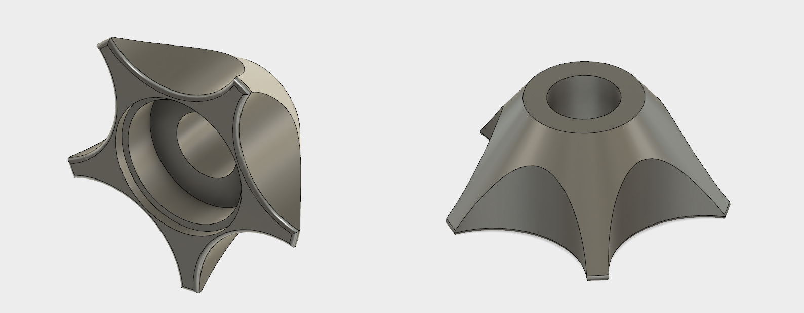
The outside diameter drives how high the spools need to be mounted off the tabletop, while the inside diameter drives the design of the piece that the spools mount onto. I had a piece of half inch steel rod that I decided to use to mount the spools on. I happened to have two bearings with an ID of nearly a half inch. A little Dremel work and they slid nicely onto the rod. I designed these little mounts to accept the flanged bearing as a press-fit. The tapered design allows it to fit a range of different spool sizes.
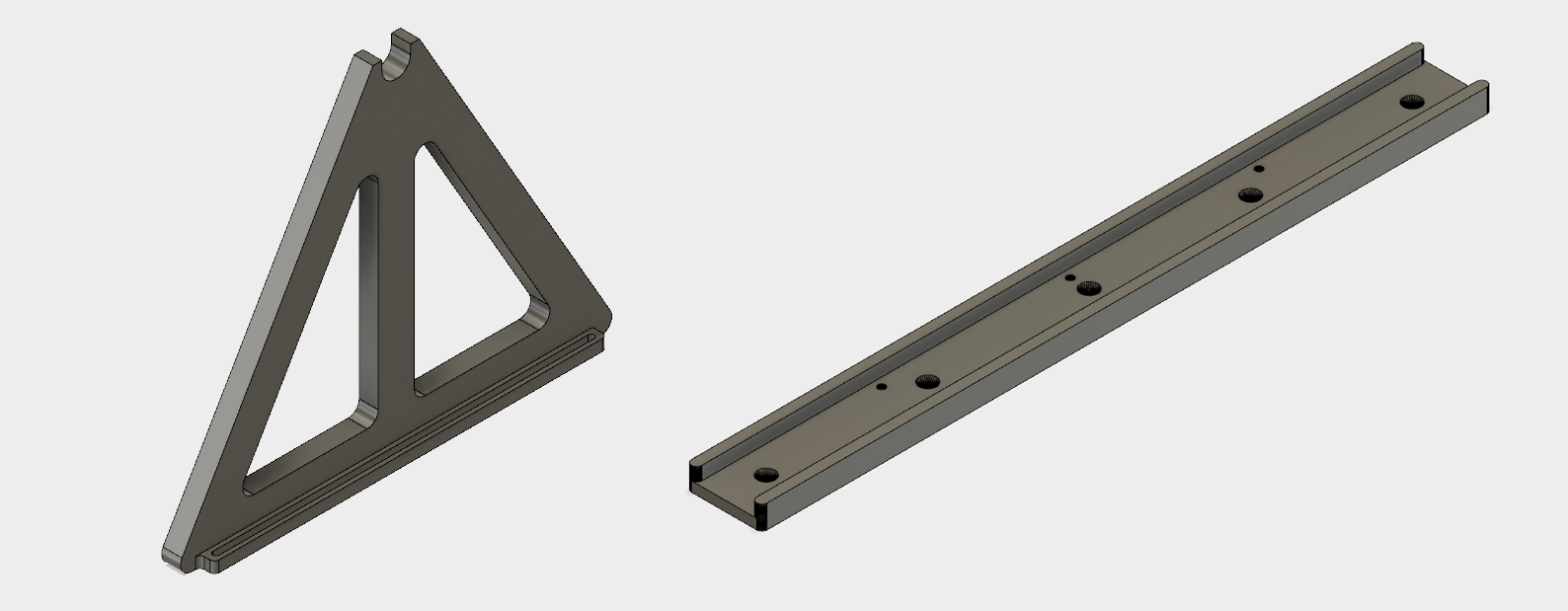
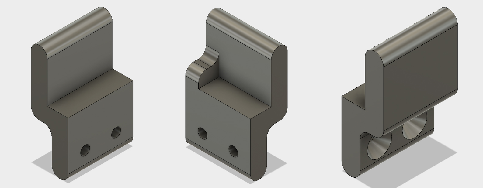
To suspend the rod in the air, I designed this bracket and corresponding slide rail mount. The concept I had here is that since I'll be making a slot in the top tabletop for the filament to go through, I want to be able to slide the filament spool forward or backwards for different spool sizes. If the spool holder was mounted in a permanant location, then small spools would have the filament traveling off the spool and then scraping the edge of the slot as they it goes through. Larger spools would have the filament curving underneath and bending sharply into the slot. The extruder motor shouldn't have to exert much force to pull more filment, so these would both be bad scenarios.
The guide rail has countersunk wood screws that screw it into the tabletop. There are locations on the bottom for nuts to press into. Bolts go through the slots at the bottom of the rod holder, through the slide rail, and then into the nuts.
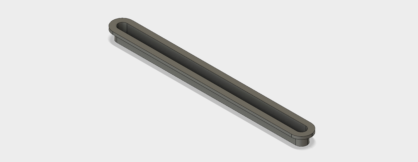
Speaking of the opening, I knew I wasn't going to be able to cut a perfect slot in the tabletop with my Dremel. I designed up this little cosmetic flange that goes in the slot in the table top and hides any imperfections in the cut. I also designed a similar flange for the slot that would be in the bottom of the tabletop (the table is actually a hollow box with some cardboard hexagonal "infill" inside for extra support). The flange for the inside of the table was wider, as the filament will be traveling to the left and right of the center of the printer.
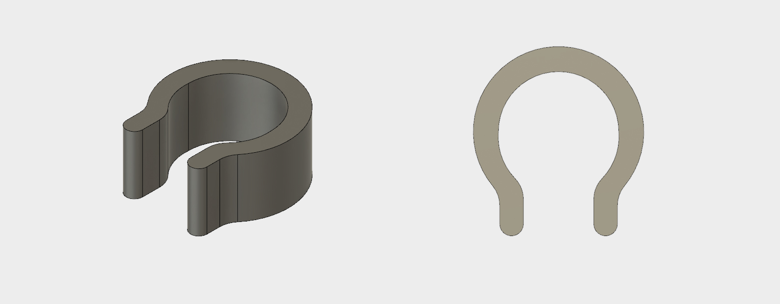
The last problem was securing the spool spindles onto the rod and keeping them from spreading apart. Since the rod wasn't threaded, I couldn't use nuts. Instead, I designed this little snap-on c-clip. I sized the middle hole just under a half inch and gave it a slightly decreasing radius as it approached the opening.
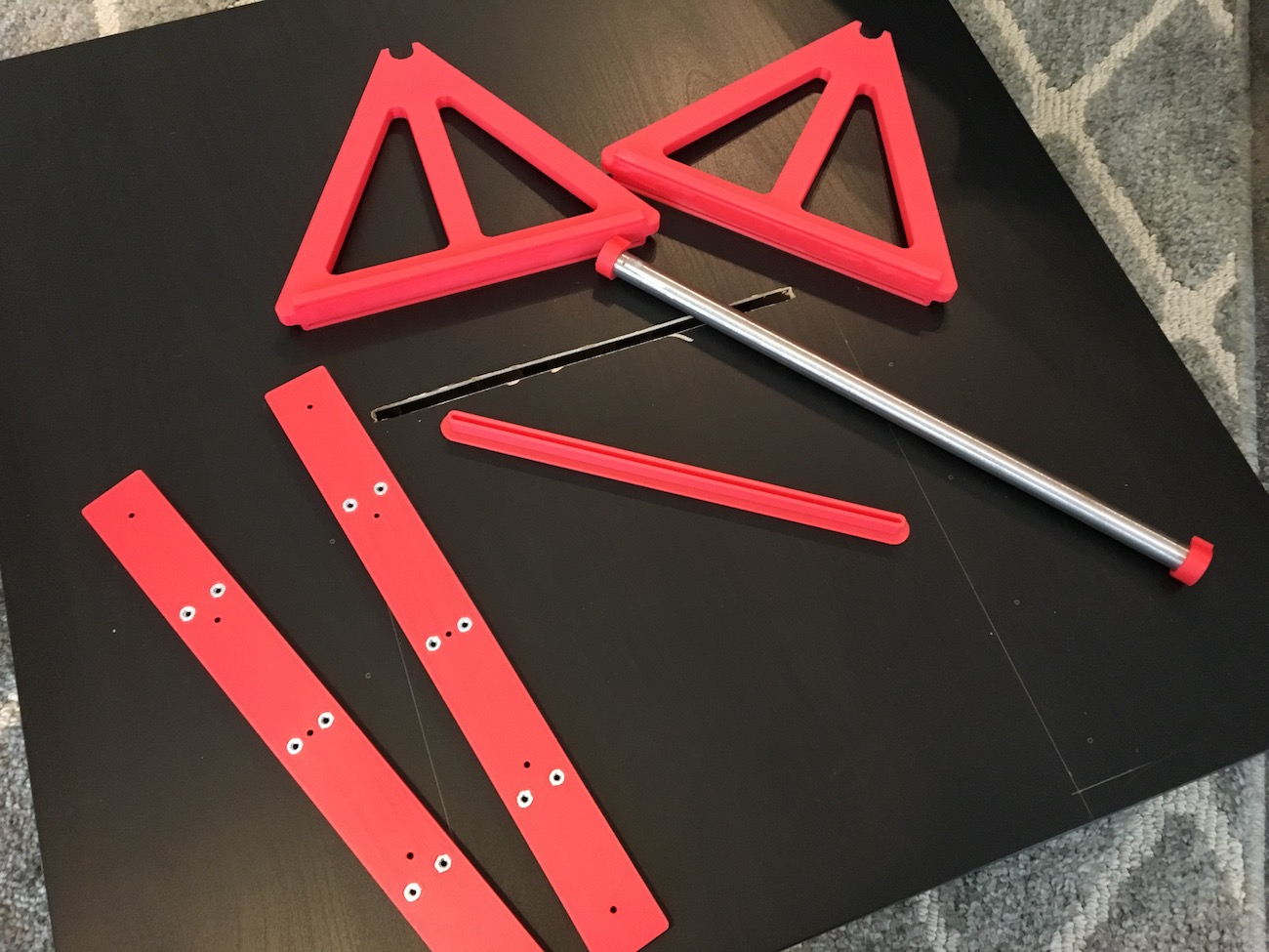
spool holder assembly
After cutting slots in the top and bottom of the tabletop the spool holder was ready to go together. Here's the holder ready to go together.
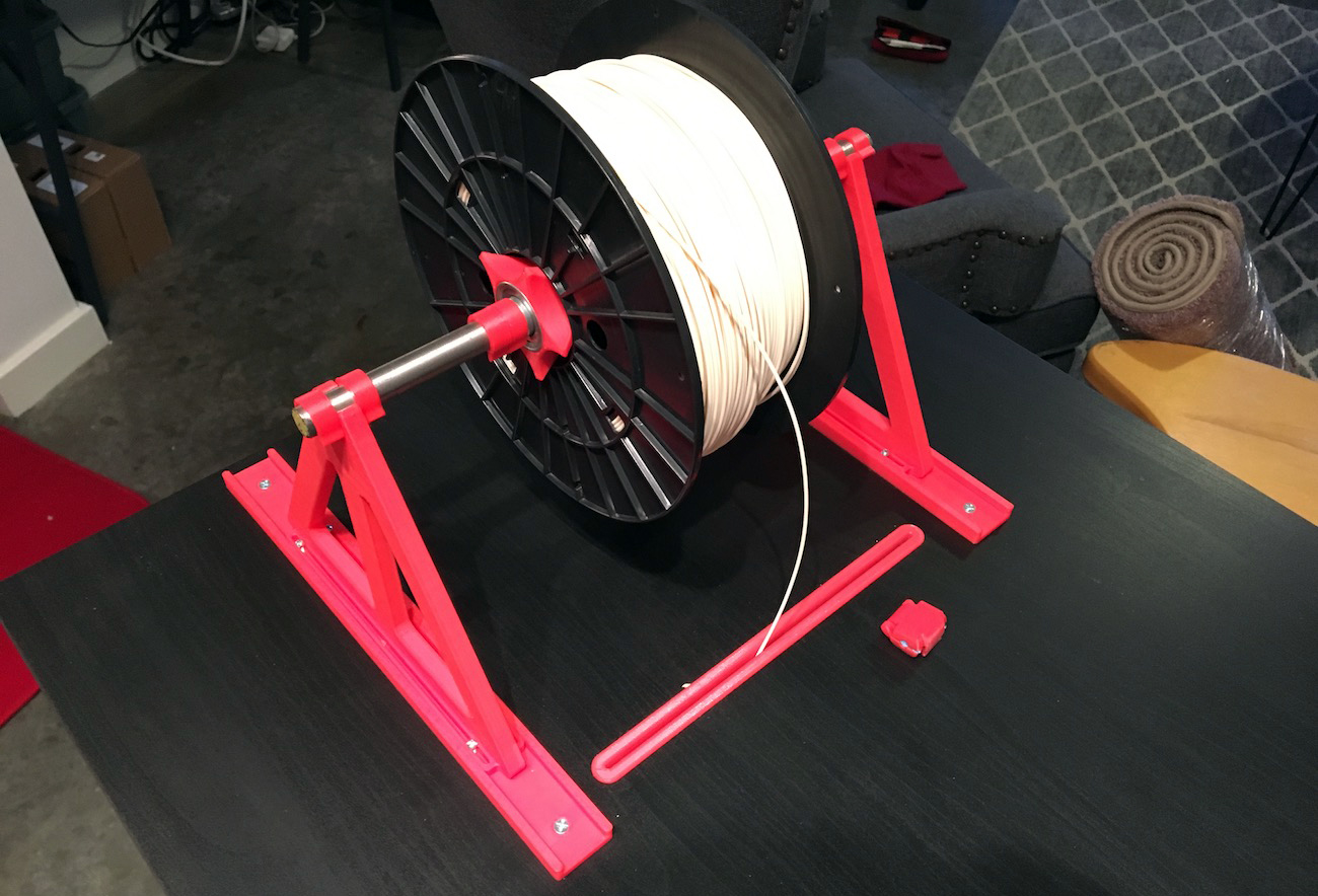
The most satisfying part of the assembly of this was the c-clips. Here's a video of them snapping on. I also test the stability of the assembly by scientifically shaking and tapping it. Seems sturdy enough.
side panel mounting design
I decided to make the side panels out of MDF instead of clear acrylic. MDF is significantly cheaper than 2x2 acrylic sheet (about 15-20 dollars a sheet). I figured I could do a small acrylic window on the front wood panel. For the side panels, I designed some mounts so that they could easily slide on and off when needed. I didn't want to secure them permanantly to the enclosure, in case I wanted or needed access or viewing of the sides of the printer.
Here's the first idea I designed. I think this is a good example of how 3D printing can make it difficult to remain constrained in design. Becuase there's very few limitiations, I went kind of wild with unneeded complications.

This design was unnecessarily large. It may have been secure, but most of the force that the mounts are going to have to exert is vertically on the edges of the MDF panels, not laterally (as if someone was pushing outwards on the panel). I needed to make 4 of these per side of the enclosure (two for the front and back of the bottom of the panel, and two for the front and back of the top of the panel), this meant I was going to be printing 12 of these. After trying to add supports to this model in Meshmixer and gauging the print times in Pronterface, I realized these would take much to long to print. Which is when I decided to rethink the design.
I reduced the mount down to the bare minimums. A flange to support the MDF panel, two screw holes, and a little support for the side of the panel. They were also designed to be printed without supports. I designed two variants, one with a "stop" and one without. The ones printed with stops would go in the "rear" of the panel, so that the panel can be slid in from one direction and doesn't slide in too far.
mounting the side panels
I used a jigsaw to cut some quarter inch MDF sheet to size. Since the Ikea tables aren't exactly precision manufactured, I eyeballed the position of the brackets, instead of drilling them in precise locations. To ensure a tight fit, I installed the bottom two mounts first, rested the panel on them, and then marked the location of the screw holes using the top brackets. If I were designing these again, I would use pan head screws instead of flat head screws. I added recesses in the mounts to countersink the flat head screws, but the screws actually ended up acting as a wedge as I tightened them. Since the holes were not perpendicular to the print layers, the wedge tries to drive apart the layers, which is a very weak dimension for 3D printed parts. I had some problems with cracking. I made sure not to over-tighten the screws.
a front window + 3d printing failure
The last piece the enclosure needed was a front panel. I again looked into acrylic for the front, but to get something that would be thick enough to act as a sturdy door (I didn't want the front panel to bend while it was being opened) was quite expensive. I instead wanted to put a smaller piece of acrylic in the middle of an MDF panel. I know this could be accomplished using traditional woodworking techniques, I again thought it would be fitting to try and print a solution. This is what I designed.
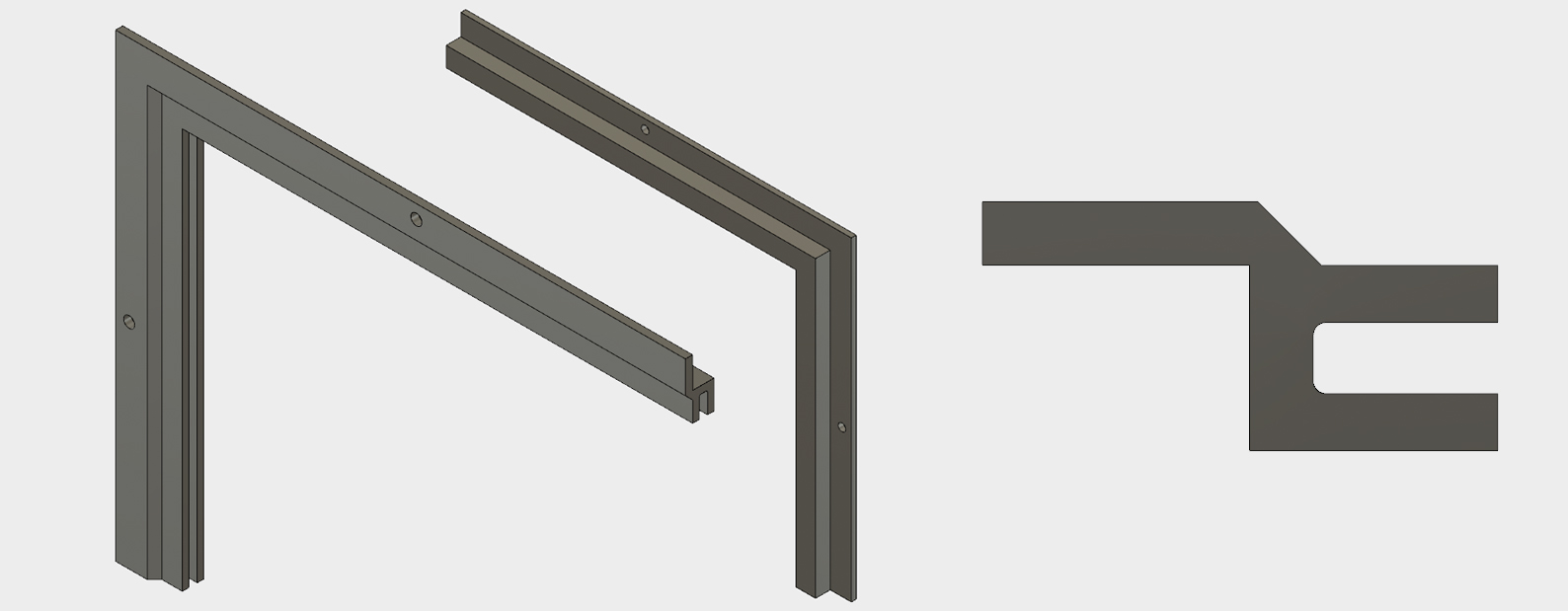
The photo shows the profile of part, as well as a quarter of the frame. The idea is that this piece is recessed into a hole in the MDF panel, and locks the sheet of acrylic inside the channel. I think it will look really nice.
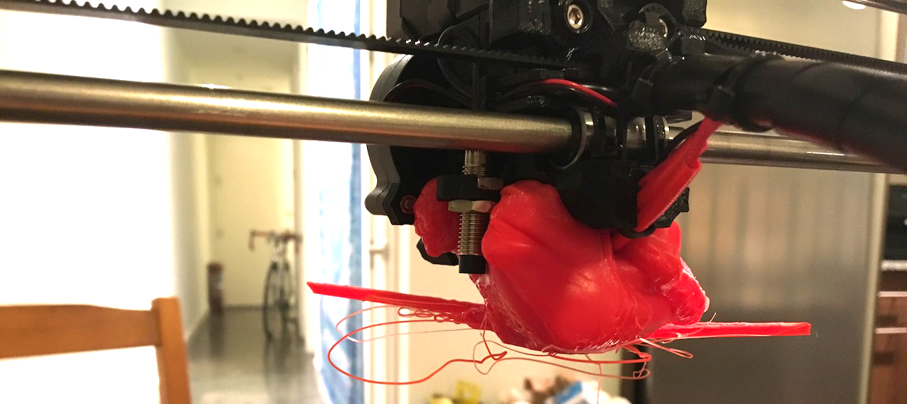
As the pieces were best printed on their sides, I decided to print it in eight sections. I printed a few test pieces that looked like they were going to work great, so I eight of them on to print before bed one night, left it alone for a few hours, and woke up to this:
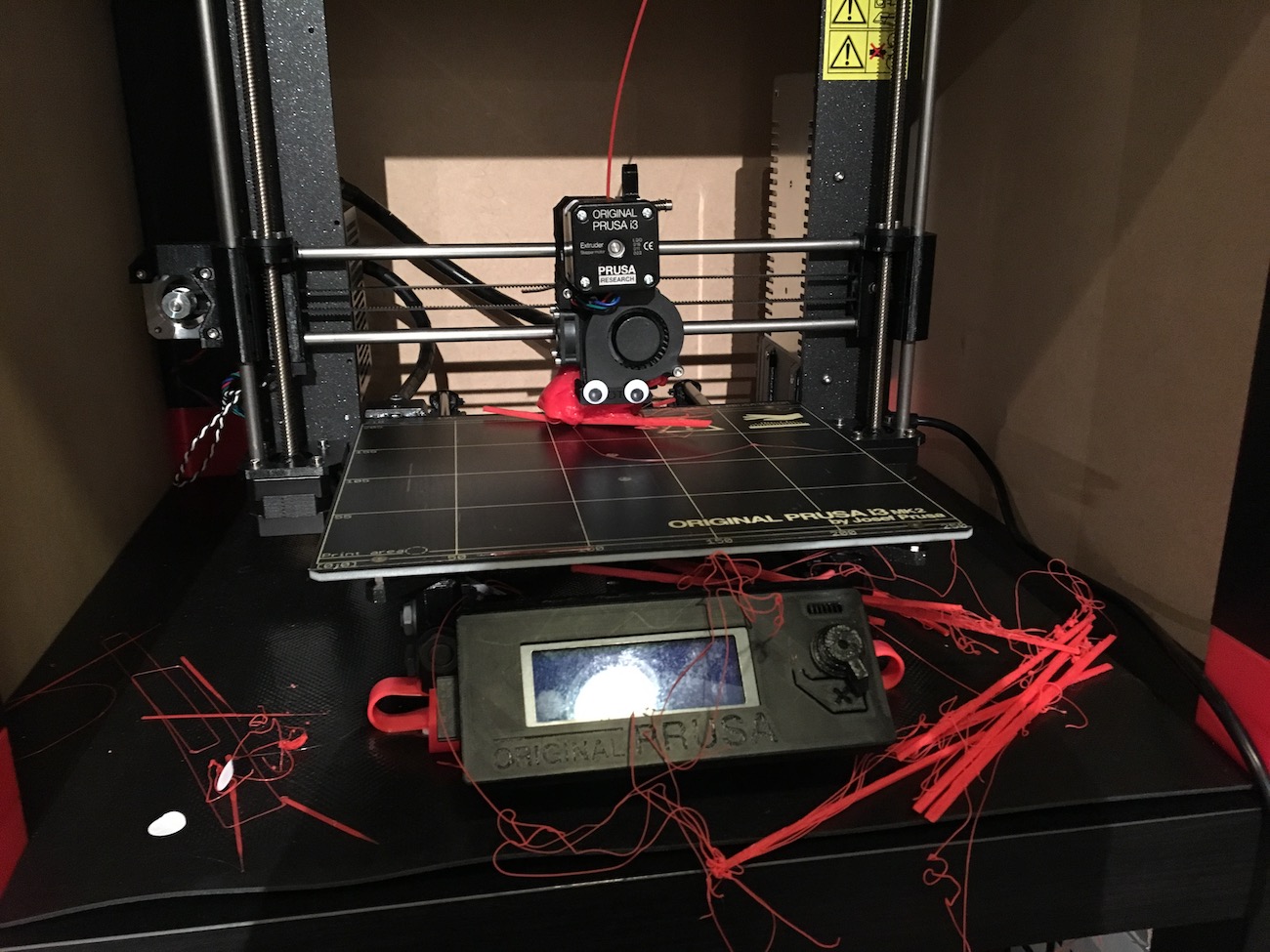
This was a complete mistake on my part. I figured that I had printed one successfully with no problems already, and there were no drastic overhangs or features I was worried about going wrong, but I certainly learned my lesson about print supervision. Unfortunately the part that lifted from the bed became stuck to the hotend heating block. It looks like this combination blocked the nozzle which then caused the extruded plastic to wrap back around onto the extruder body. I thought it would be an easy fix until I noticed that the thermistor and heating element wires were both entombed in the blob of plastic.
I tried multiple techniques at the reccomendation of the Prusa online community. The first was heating the hotend up to PLA temperatures and waiting for the heat to break the hotend free. I think the block was too large for the hotend to heat to a uniform temperature, so this didn't get me far. I tried sawing at it, which didn't do much. I also tried submerging the entire assembly in boiling water (which made the plastic a little malleable). This also wasn't too successful, it became very difficult to handle to exert force on the extruder since the boiling water also heated up the heatbrake. What I ended up doing was setting the hotend temperature to around 275°C, much higher than PLA's printing temperature. This allowed me to push on the heatbrake and essentially "melt" the hotend through the blob of plastic.
While this worked, there's still plastic on every surface of the hotend and heatbrake, which I'm not sure how to remove. I may try and clean this extruder assembly up as good as possible to keep as a spare and order some new parts from E3D to install. Unfortunately for now, this project is halted.
02/10/2017
3D printing a new backpack strap buckle
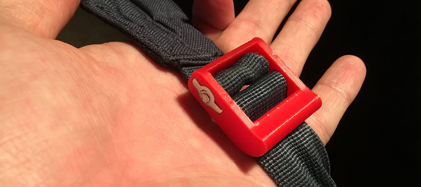
My backpack strap buckle just broke, and I've been walking around with the upper and lower straps tied to one another, meaning my backpack straps aren't adjustable anymore. Here's a picture of the existing buckle.
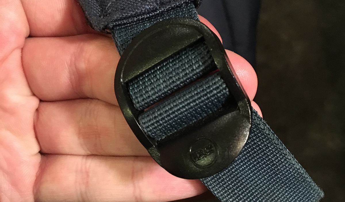
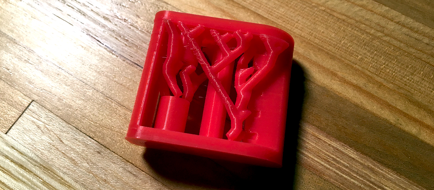
While there are replacements online, the top strap loop is sewn into the buckle. Though I could cut it and thread it into a new buckle, I wasn't confident I would be able to sew the nylon strap and have it be as strong as the factory seam. I thought I could print a new buckle that would allow for the loop to be threaded in and then secured with a bolt for strength. Here's what I came up with, one of my first designs in Fusion360, which I'm enjoying, but still getting used to.
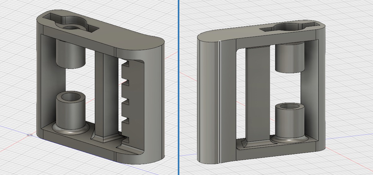
This is where I think 3D printing is beautiful. I didn't have a normal bolt and nut of the correct size, all I had was a toggle bolt in my odds and ends box. The toggle bolt has a little threaded insert in the middle of the "wings" of the toggle, which I removed using some pliers. I dimensioned the insert out and made an indention in one side of the buckle design. I also designed the width of the buckle around the length of the bolt, so that I wouldn't have too much bolt sticking out of the nut.
The design has a lot of overhangs, mainly the big cylinder which the bolt passes through, the teeth of the cinch part, and the curved edge of the top surface (which is unbridgeable). I could have used the built-in supports in Slic3r or Cura, but I've been hearing a lot about these tree supports in Autodesk's Meshmixer so I decided to give them a try. Here's what meshmixer came up with.
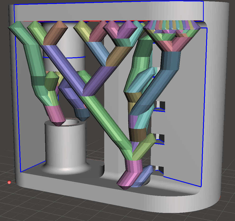
Here's how the part came out on the printer, and the supports separated with ease. I was very surprised the tiny stems of the trees didn't collapse during the print.
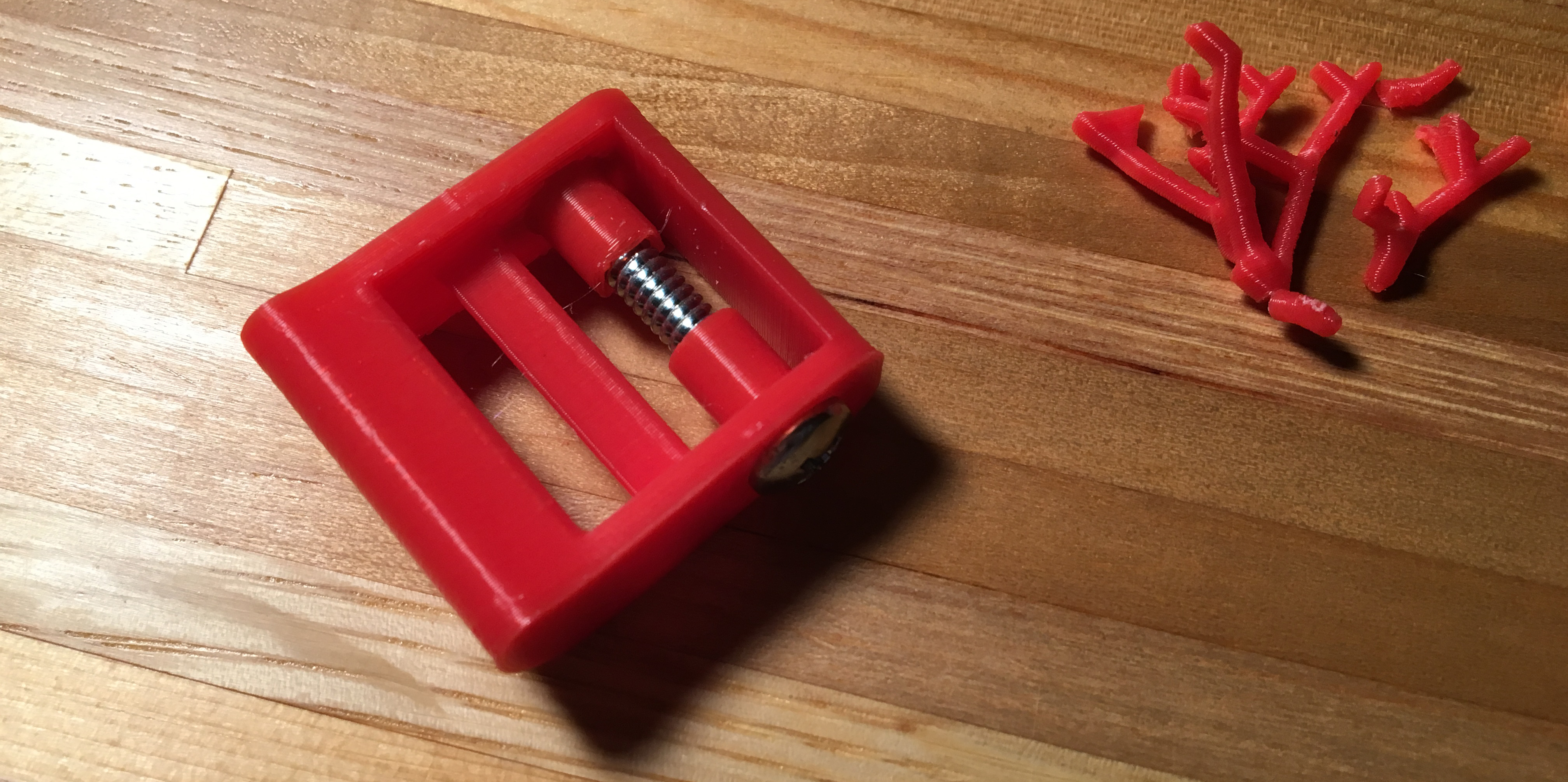
The toggle bolt insert popped right in to the recess I modeled (which was very satisfying). I was able to squeeze the nylon loop between the opening between the bolt sheath in the buckle, then expand it over the sheaths, before sliding the bolt through. The whole thing works a charm.
02/5/2017
prusa i3 mk2 assembly + first prints
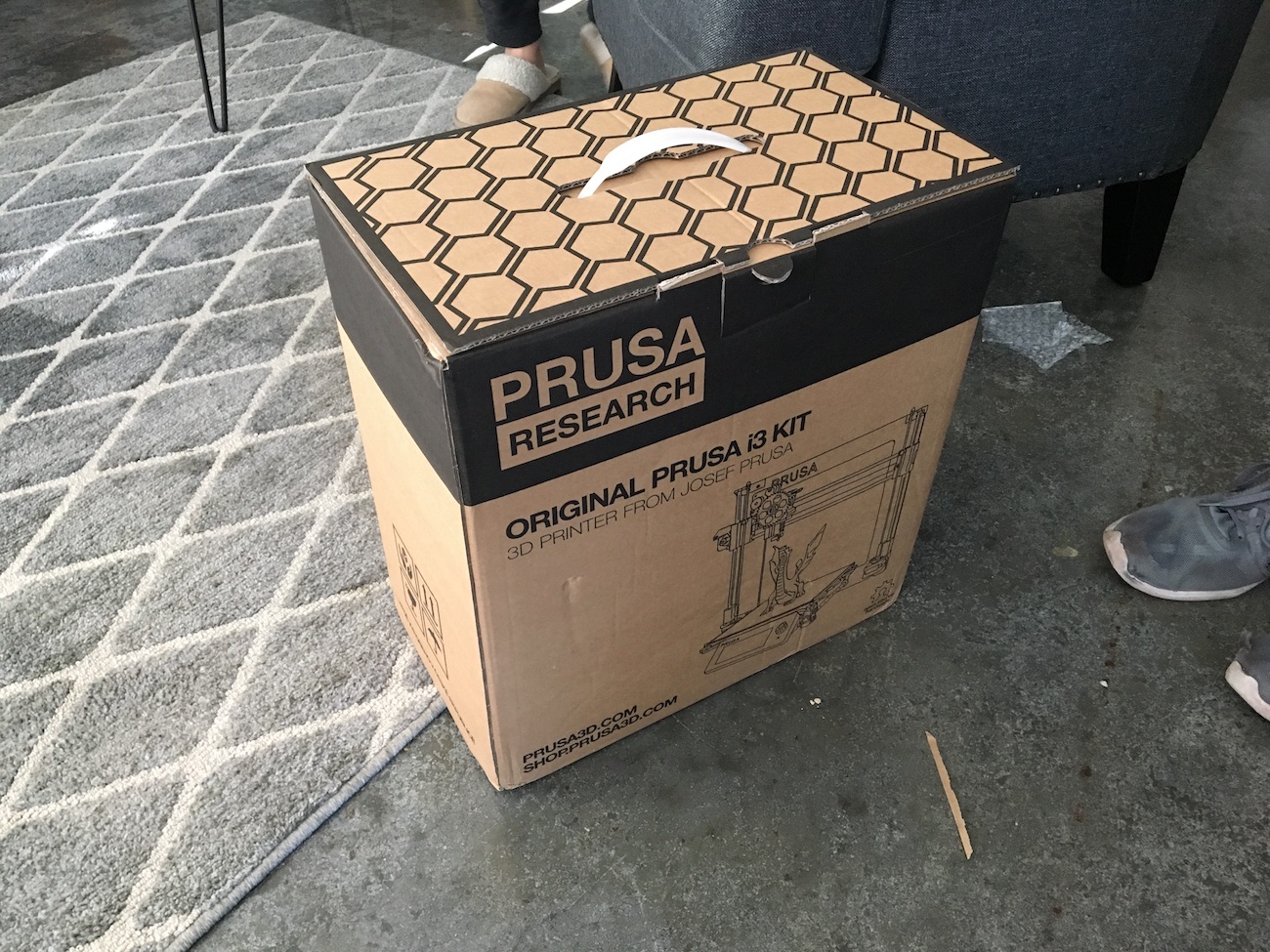
After a few months of waiting, my Prusa i3 mk2 finally turned up in the mail!
I deliberated a lot over which printer to order, and while there's really not a best choice, the Prusa i3 might be close. It's a hard balance between price, convenince, support and reliability. I wanted something that I didn't have to tinker with too much to get to print, since my main reason for wanting a 3D printer was not to have a 3D printing hobby, but to make things. -- I wouldn't want a drill that I had to re-assembly every time I wanted to drill a hole.
The kit is of incredibly good quality. Each step in the manaul has an individually labeled bag of printed parts and bag of hardware. The bags have an inventory on them to make sure you have everything needed. The inventory is even in 1:1 scale, to help identify different length bolts and different sized nuts. The instructions themselves were excellent. I only had some trouble in one or two places where I tried to get ahead of the manual.
There was only about ten hours between opening the box and taking my first print off the bed, including coffee and dinner breaks. You can see a timelapse of the build and first print in the video below, the latter half of which involves me watching Seinfeld. One of my best friends (and 3D printing veteran) Austin was with me for the first half of the build, which made it super fun.
(I didn't have a tripod or anything to mount my iPhone on to take the timelapse, but I did have some spare 1x6 and 1x4, a toggle bolt (no wood screws at the time) and some zipties. So I created this makeshift bipod which worked a charm.)
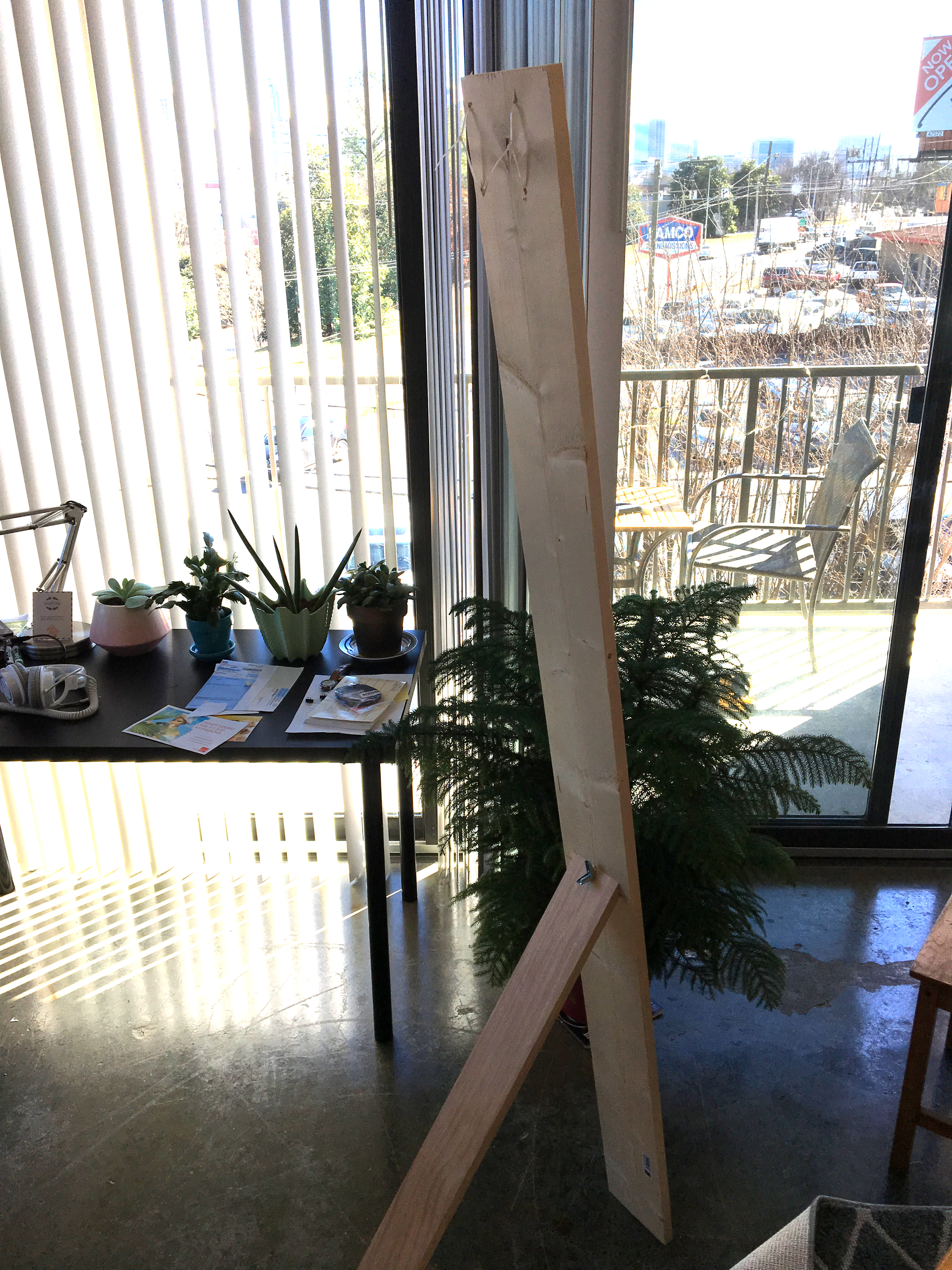
The only issues I had during the construction was forgetting to embed a nut in the extruder assembly, which made me take the assembly almost completely apart to get the nut in the right place. I also had some issues routing all of the wires that come off of the extruder through their channels, but after some fanagling it was just fine. I also had a brief scare when turning the printer on for the first time: I couldn't get past the language selection screen. Turns out I kept hitting the "X" button on the front panel, which does a hardware reset on the driver board. It took a quick Google to realize that the rotary knob also has a button built in. At least I wasn't alone.
test prints
So the first print I did was the included Prusa logo badge, which helped me get through the process of adjusting the live-z value correctly. The printer has an inductive probe to measure any XY skew in the printer frame as well as any warping of the bed, but it needs a reference height to tell it exactly where it is above the bed. The process of setting this for the first time was a bit nerve-racking as the hotend looks as it's going to plunge directly into the bed while doing a Z traverse. Here's a video from Prusa themselves explaining the concept behind their calibration method.
![]()
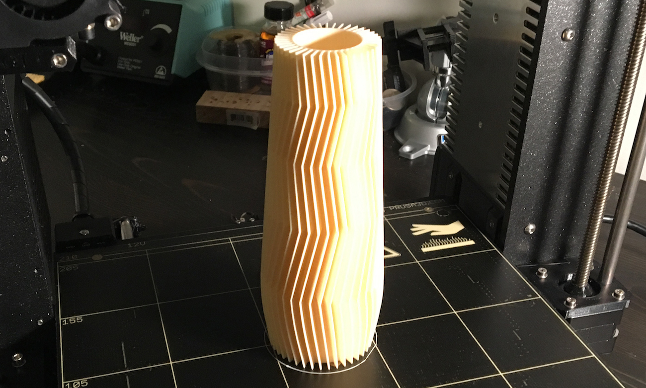
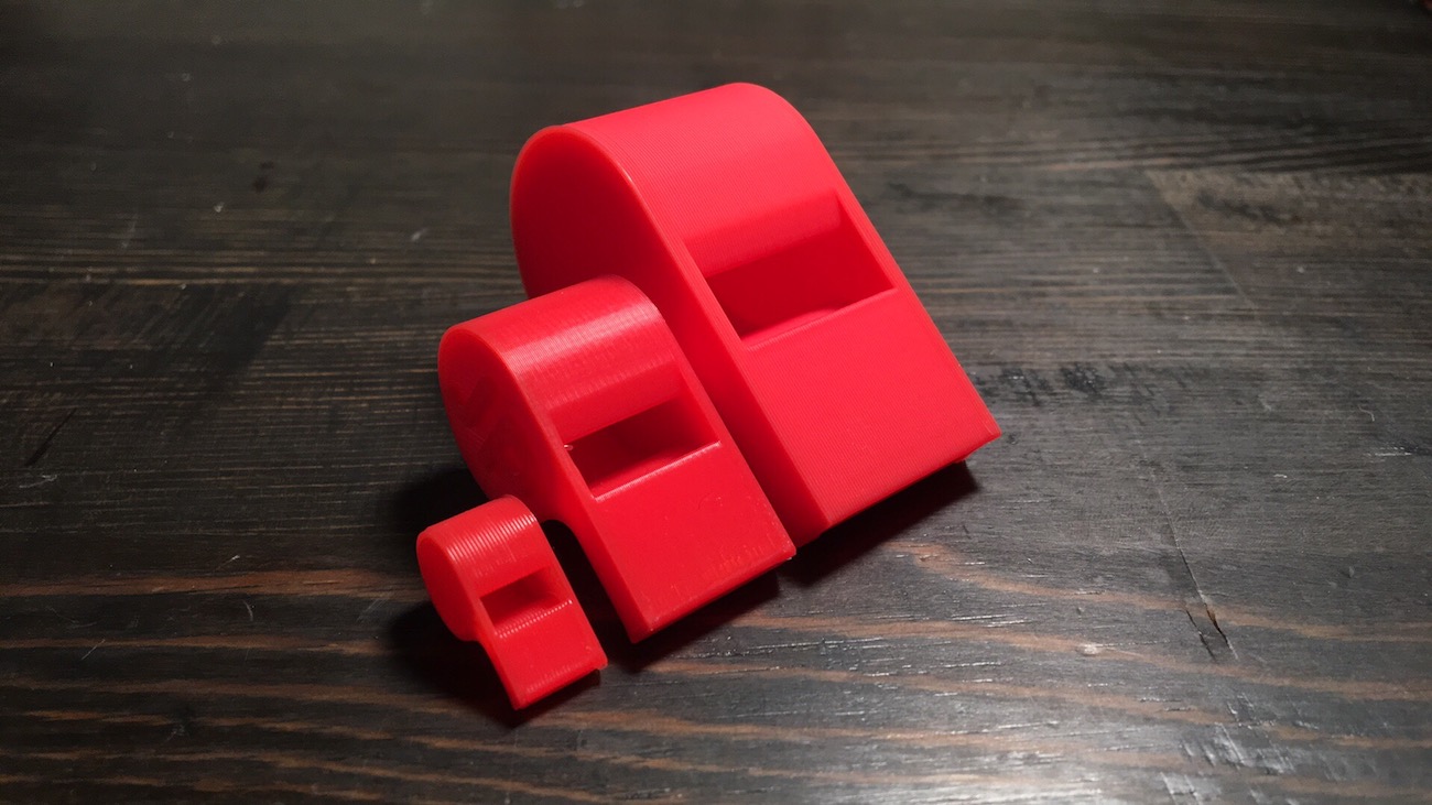
I also printed the whistle that was included, which was my first time watching the printer pull off a bridge, very exciting. The last thing I printed before trying one of my own models was this vase, which blew me away. It took about seven or eight hours of print time, which it handled no problem. There was very little banding on the print, which I was really excited about.
designing + slicing + printing
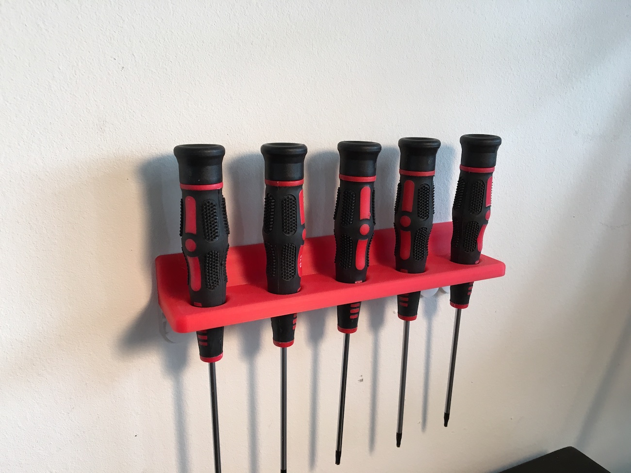
I wanted to print something of my own, but didn't have anything ready. I looked around and thought my torx drivers could deserve not being on my desk anymore, so I modeled up this little holder in Solidworks. I'd already used Slic3r a bit, so I loaded in the Prusa provided material and slicing presets and I was off. Very, very easy. Seeing something on your computer screen and then holding it in your hands just a few hours later might never get old.
I also played a bit with modifying meshes in Fusion360 (something I've used very little of before) to remove the "JP" initials from the whistle model that shipped with the printer (sorry Josef). I printed two more whistles at 150% and 50% size, which was very fun. The small one took less that ten minutes to print.
I don't have much more to report, other than I'm extremely happy with my purchase and I can't wait to print more stuff.